Advertisement
Quick Links
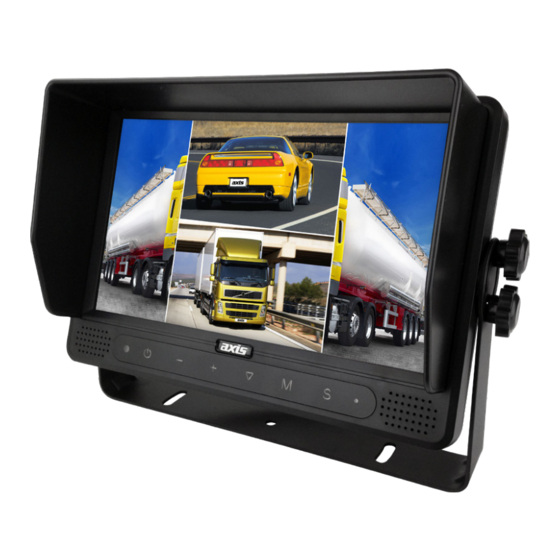
JS1409Q
9" TOUCHSCREEN QUAD VIEW MONITOR
SPECIFICATIONS
MONITOR
- LCD:
- Resolution:
- Touch Screen:
- Touch Buttons:
- Backlighting Adjustment:
- System Format:
- Onboard Loudspeaker:
- Mirror Orientation:
- Camera Image Display Mode:
- Camera Image Adjustment:
- Menu Languages:
- Trigger Lines:
- Trigger Priority:
- Auto Scan:
- Reverse Warning Gauge:
- Automatic Start-up:
- Automatic Switch to Trigger CH:
- Input:
- Output:
- Operating Voltage Range:
- Short-Circuit Protection:
- Dimensions:
9"
800 x 480 RGB (60Hz)
Resistive Touch
Can recognize up, down, left, right side "swipe"
Two-Point touch for channel switching
Yes
4 Manual Levels, 1 Auto Level
PAL/NTSC
Yes
Horizontal, Vertical, Horizontal-Vertical, Off
Single (Left/Right/Front/Back), Dual, Triple, Quad,
Picture In Picture (1/2/3), Trefoil, H-Split, Y-Split
Brightness, Contrast, Colour, Tint
English, Francais, Nederlands, Espanol, Deutsch, Italiano
5
Yes
Yes
Yes
Yes when triggered under standby
Yes
4 x 4-PIN, 1 x AUX Audio
2 x RCA Video, 1 x RCA Audio
10-32V
Yes
232W x 157H x 40D mm
INSTRUCTION MANUAL
INCLUDED
- Robust Bracket
- Stand Mount
- Sun Cover
- IR Remote
2
YEAR WARRANTY
Advertisement

Related Manuals for Axis JS1409Q


Summary of Contents for Axis JS1409Q
- Page 1 INSTRUCTION MANUAL JS1409Q 9” TOUCHSCREEN QUAD VIEW MONITOR SPECIFICATIONS MONITOR INCLUDED - LCD: 9” - Robust Bracket - Resolution: 800 x 480 RGB (60Hz) - Stand Mount - Touch Screen: Resistive Touch - Sun Cover Can recognize up, down, left, right side “swipe”...
- Page 2 Contents …… ………………………………………………………… 1 Products …………………………………………… Monitor Installation …………………………………………… Connections ……………… ……………………………………… Controls ……………………………………………… ……… Operation Important Information …………………………………………. . 1. Products MUTE POWER MENU MODE SEL. REST Monitor Sun Shield IR Remote Control U-Support Bracket & AV and Power Supply Centre Mount Bracket Conversion Cable Angle Adjustment Screws...
- Page 3 2. Monitor installation Centre Mount Bracket Any display mode 5.4.7 VOL- RIGHT BACK Any display mode 5.4.8 VOL+ RIGHT BACK...
- Page 4 3. Connections 4P Green 3A Fuse R CA Yellow R CA White RC A Green 3.5MM AUX Connector Left Camera Right Camera Front Camera Back Camera Red: Power White: Trigger 1 Black: Ground Blue: Trigger 2 Brown: Trigger 4 Green: Trigger 3 Yellow: Split VIDEO OUT AUDIO OUT...
- Page 5 4. Controls IR Signal Sensor Power key The Original The mode set in display mode the main menu Automatic low light sensor...
- Page 6 5. Operation 5.1 OSD Setting MAIN MENU MAIN MENU CAMERA SETUP CAMERA SETUP SETUP SETUP SYSTEM SETUP SYSTEM SETUP TRIGGER SETUP TRIGGER SETUP TRIGGER PRIORITY TRIGGER PRIORITY RESET RESET SETUP REAR GAUGE INPUT SCAN BOUNDARY WHITE 5.2 Trigger Setting MAIN MENU MAIN MENU CAMERA SETUP...
- Page 7 5.3 Jump Key Setting MAIN MENU MAIN MENU CAMERA SETUP CAMERA SETUP SETUP SETUP SYSTEM SETUP SYSTEM SETUP TRIGGER SETUP TRIGGER SETUP TRIGGER TRIGGER PRIORITY PRIORITY RESET LEFT H-SPLIT SYSTEM SETUP REC-V OUT QUAD SCAN RIGHT TREFOIL SCAN DELAY 01 SEC JUMP KEY LEFT FRONT...
- Page 8 Touch Screen 5.4.1 Any multi mode TOUCH MENU AREA RIGHT LEFT LEFT BACK FRONT TOUCH MENU AREA LEFT RIGHT BACK FRONT LEFT Any display mode 5.4.2 TOUCH Touch Touch Original display mode The display mode which you set in main menu Touch IIIIIIIIIIIIIII Press to adding/decrease the brightness level.
- Page 9 MAIN MENU CAMERA SETUP ( 5 ) SETUP SYSTEM SETUP TRIGGER SETUP Touch TRIGGER PRIORITY RESET Touch again origin display mode Channel or item on menu selection up/down Item on menu selection decrease/adding 5.4.3 Any multi mode Touch RIGHT BACK RIGHT LEFT Touch...
- Page 10 Any display mode 5.4.5 fast (lift off) Display mode selection Last position BACK RIGHT Prevbus position Any display mode 5.4.6 fast (lift off) Display mode selection Last position BACK RIGHT Prevbus position Any display mode 5.4.7 VOL- RIGHT BACK Any display mode 5.4.8 VOL+ RIGHT...
- Page 11 Important Information Wiring Information When any of the five trigger wires are connected to a positive voltage source (10-32V), this unit will automatically display the camera(s) associated with the triggered wire. To trigger more than one camera simultaneously, use the yellow ‘split’ wire. The cameras to be displayed when this wire is triggered can be set in the menu.
- Page 12 Please complete details below in the event of warranty service being required. Purchaser's Name: _________ _ Purchaser's Address: ________ _______ _ JS1409Q Model Number: ________ Serial Number: __ _ Dealer Name: _ _ _ _ _ _ _ _ _ Date of Purchase:...
Need help?
Do you have a question about the JS1409Q and is the answer not in the manual?
Questions and answers