Table of Contents
Advertisement
Quick Links
702A Single-Party Indoor 115 V AC
Confidentiality Notice
This manual is provided solely as an operational, installation, and maintenance guide and contains sensitive
business and technical information that is confidential and proprietary to GAI-Tronics. GAI-Tronics
retains all intellectual property and other rights in or to the information contained herein, and such
information may only be used in connection with the operation of your GAI-Tronics product or system.
This manual may not be disclosed in any form, in whole or in part, directly or indirectly, to any third party.
General Information
This manual applies to the GAI-Tronics 702A Single-Party Indoor 115 V AC Amplifier Enclosure, which
is an important component of the 700 series Page/Party
party systems.
The 702A Enclosure is constructed of fabricated steel, and is equipped with terminal strips for connecting
the system cable. The 701 and 751 series amplifiers mate directly with this enclosure.
Installation
CAUTION
Do not install this equipment in hazardous areas other than those indicated on
the approval listing in the Specification section of this manual. Such installation may cause a safety
hazard and consequent injury or property damage.
When installing an add-on station, consult the system layout diagram at the end of this manual. This
figure, when used in conjunction with the station installation information and cable layout guide, should
provide all the information necessary to install additional Page/Party stations.
Enclosure Placement
All GAI-Tronics Page/Party
required for each installation. GAI-Tronics multi-conductor cable, designed especially for this application,
is recommended. The number, size, and color-coding of conductors are listed in the accompanying system
connection diagrams.
System layout and power cable length are very important when installing Page/Party equipment.
Although it varies for different systems, the general guideline is that the total power cable length should not
exceed one mile (5280 feet) for 115 V ac systems. The total cable length is the most important
consideration while cable length between the stations is generally not a factor.
GAI-TRONICS 3030 KUTZTOWN RD. READING, PA 19605 USA
V
ISIT WWW
G A I - T R O N I C S ®
A H U B B E L L C O M P A N Y
Amplifier Enclosure
®
units are wired in parallel. Good system layout design minimizes the cable
610-777-1374
800-492-1212
.
-
.
GAI
TRONICS
COM FOR PRODUCT LITERATURE AND MANUALS
®
system. This enclosure is configured for single-
Fax: 610-796-5954
Pub. 42004-138L
Advertisement
Table of Contents

Related Manuals for Hubbell GAI-TRONICS 702A


Summary of Contents for Hubbell GAI-TRONICS 702A
- Page 1 This manual may not be disclosed in any form, in whole or in part, directly or indirectly, to any third party. General Information This manual applies to the GAI-Tronics 702A Single-Party Indoor 115 V AC Amplifier Enclosure, which ® is an important component of the 700 series Page/Party system.
- Page 2 Pub. 42004-138L 2 of 7 702A Single-Party Indoor 115 V AC Amplifier Enclosure Page: Mounting The 702A Enclosure is not supplied with conduit or cable openings. Drill or punch these openings using the template supplied before mounting the enclosure. The recommended cable entry point is via the bottom of the enclosure near the rear surface to prevent moisture from dripping onto the terminals or PCBAs.
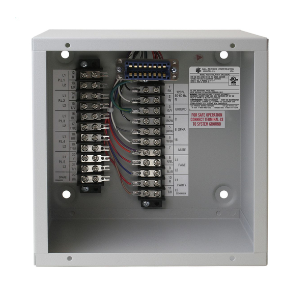
- Page 3 Pub. 42004-138L 3 of 7 702A Single-Party Indoor 115 V AC Amplifier Enclosure Page: Wiring Attach the conduit to the enclosure. Feed the wiring through the conduit and bring it into the enclosure. See Figure 2. Follow the wire colors carefully because the colors correspond to GAI-Tronics 60038 Series cable.
- Page 4 Pub. 42004-138L 4 of 7 702A Single-Party Indoor 115 V AC Amplifier Enclosure Page: Figure 2. Wiring Diagram f:\standard ioms - current release\42004 instr. manuals\42004-138l.doc 04/09...
- Page 5 Pub. 42004-138L 5 of 7 702A Single-Party Indoor 115 V AC Amplifier Enclosure Page: Maintenance Regular inspection and a good preventive maintenance program will increase the reliability of your GAI-Tronics station. The GAI-Tronics Field Service Department can formulate a service contract suited to your facility’s specific need for preventive maintenance.
- Page 6 Pub. 42004-138L 6 of 7 702A Single-Party Indoor 115 V AC Amplifier Enclosure Page: Specifications Construction/finish..............16-gauge cold-rolled steel/gray polyurethane Mounting................Wall or column, four 5/16-inch mounting holes Connections ................Internal screw-type barrier terminal blocks Dimensions.............. 8.1 H × 8.1 W × 5.1 D inches (206 × 206 × 129 mm) Shipping weight ........................
- Page 7 Pub. 42004-138L 7 of 7 702A Single-Party Indoor 115 V AC Amplifier Enclosure Page: f:\standard ioms - current release\42004 instr. manuals\42004-138l.doc 04/09...
- Page 8 Warranty Equipment. GAI-Tronics warrants for a period of one (1) year from the date of shipment, that any GAI-Tronics equipment supplied hereunder shall be free of defects in material and workmanship, shall comply with the then-current product specifications and product literature, and if applicable, shall be fit for the purpose specified in the agreed-upon quotation or proposal document.
Need help?
Do you have a question about the GAI-TRONICS 702A and is the answer not in the manual?
Questions and answers