Advertisement
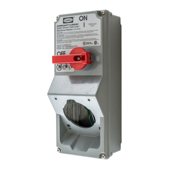
SAFETY-SHROUD TWIST LOCK
GENERAL INFORMATION
CAUTION: Risk of electric shock. More than one disconnect switch may be required to de-
energize this equipment before servicing. Disconnect ALL power supplies to enclosure
before exposing interior.
NOTICE: For installation by a qualified electrician in accordance with national and local Electrical
codes and the following instructions.
NOTICE: Receptacle MUST be re-installed BEFORE connection to power supply.
30 Amp Maximum receptacle rating. See ratings table and wiring diagrams.
NOTICE: This enclosure must NOT be used as a junction box for feed-through connections.
NOTICE: Separate overcurrent protection must be provided in accordance with
National Electrical Code® Article 220 or Canadian Electrical Code, Section B, as appropriate.
Overcurrent protection MUST NOT exceed the ampere rating of the receptacle. [Ref. National
Electrical Code®, Part 1, Rule 430-42(c) or Canadian Electrical Code®, Subrule 28-602(3)(c)(i)].
Suitable for use on a circuit capable of delivering not more than 10,000 rms symmetrical amperes at
the voltage rating of the receptacle.
This enclosure includes a lockout provision: ON-OFF control knob (in the OFF position) accepts up
to 5/16 inch (8mm) diameter shackle of a suitable padlock. Lockout device to isolate energy from
the connected equipment as a method of compliance to OSHA Lockout/Tagout Regulation 29 CFR
Part 1910.147. This feature however, does NOT isolate the power supplied to the enclosure during
internal servicing of the enclosure.
MO UNT I NG I NST RUCT IO NS
(1.) Remove the four (4) cover mounting screws and remove the old cover. Switch handle must be
"off" to remove cover.
(2.) Disconnect wiring to receptacle. Remove the four (4) receptacle mounting screws and remove it
from the old cover.
Wiring Device-Kellems
Hubbell Incorporated (Delaware)
Shelton, CT 06484
1-800-288-6000
www.hubbell-wiring.com
PD2587
(Page 1)
10/13
HUBBELL CIRCUIT - LOCK™
®
MECHANICAL INTERLOCK REPLACEMENT COVER
Installation Instructions
Advertisement
Table of Contents

Related Manuals for Hubbell Circuit-Lock


Summary of Contents for Hubbell Circuit-Lock
-
Page 1: Installation Instructions
HUBBELL CIRCUIT - LOCK™ ® SAFETY-SHROUD TWIST LOCK MECHANICAL INTERLOCK REPLACEMENT COVER Installation Instructions GENERAL INFORMATION CAUTION: Risk of electric shock. More than one disconnect switch may be required to de- energize this equipment before servicing. Disconnect ALL power supplies to enclosure before exposing interior. - Page 2 HUBBELL CIRCUIT - LOCK™ ® SAFETY-SHROUD TWIST LOCK MECHANICAL INTERLOCK REPLACEMENT COVER WI RI NG I NST RUCT I O NS (3.) Refer to the receptacle wiring instructions and re-connect wiring to the receptacle. Tighten the terminal screws to 18 pound inch (2.0 N•m) TAKE CAUTION THAT THERE ARE NO STRAY WIRE STRANDS.
Need help?
Do you have a question about the Circuit-Lock and is the answer not in the manual?
Questions and answers