Table of Contents
Advertisement
Available languages
Available languages
Quick Links
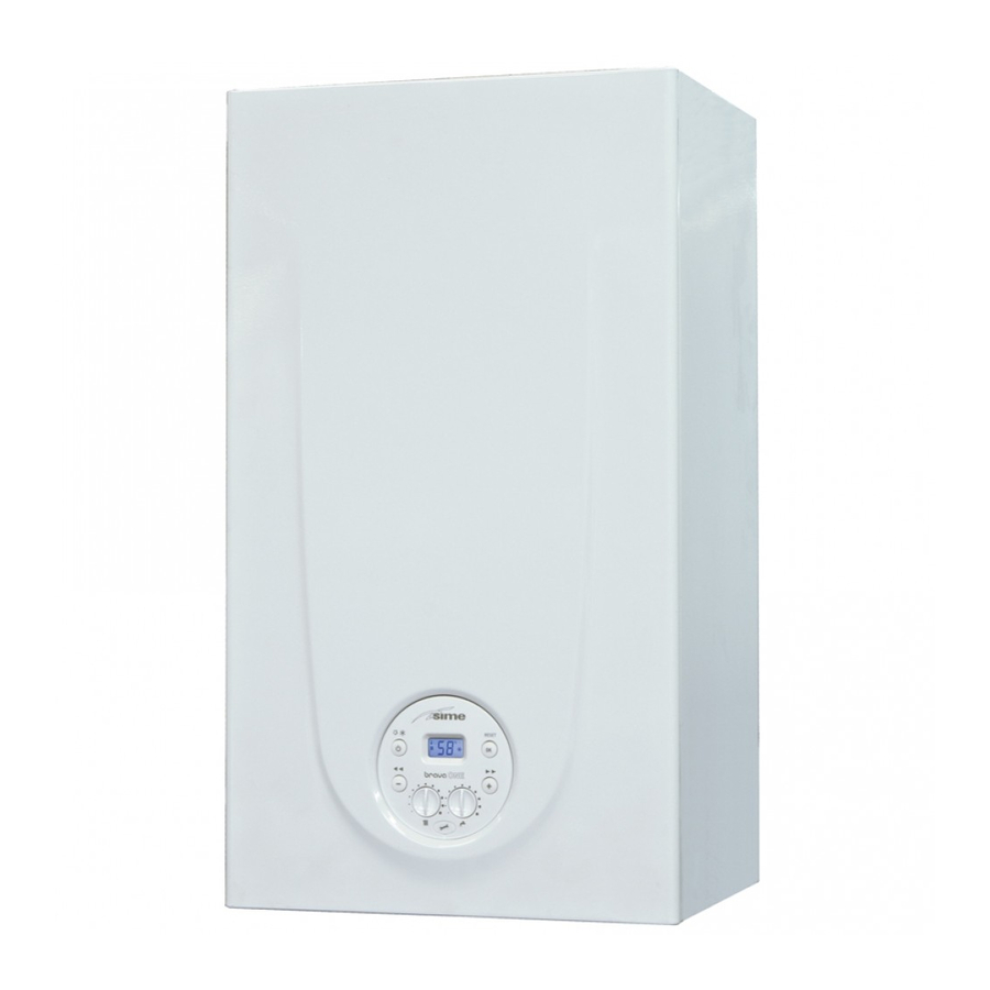
Chaudières murales à basse température
Low temperature wall mounted boiler
BRAVA ONE BF
MANUEL POUR L'UTILISATION, L'INSTALLATION ET L'ENTRETIEN
USER, INSTALLATION AND SERVICING INSTRUCTIONS
FR
EN
Pour consulter la documentation,
visitez notre site web www.sime.it
To consult the documentation, visit our
website www.sime.it
Fonderie SIME S.p.A.
6328416 - 12/2021 - R1
TRADUCTION DES INSTRUCTIONS ORIGINALES - TRANSLATION OF THE ORIGINAL INSTRUCTIONS
Advertisement
Chapters
Table of Contents

Related Manuals for Sime BRAVA ONE BF


Summary of Contents for Sime BRAVA ONE BF
- Page 1 Low temperature wall mounted boiler BRAVA ONE BF MANUEL POUR L’UTILISATION, L’INSTALLATION ET L’ENTRETIEN USER, INSTALLATION AND SERVICING INSTRUCTIONS Pour consulter la documentation, visitez notre site web www.sime.it To consult the documentation, visit our website www.sime.it Fonderie SIME S.p.A. 6328416 - 12/2021 - R1...
- Page 2 - fermez les robinets du combustible et de l'eau de l'installation hydrique. – se réserve le droit Fonderie SIME S.p.A. de modifier à tout moment et sans pré- – Afin d'assurer une efficacité optimale avis ses propres produits afin de les...
- Page 3 INTERDICTIONS IL EST INTERDIT IL EST INTERDIT – L’usage de l'appareil par des enfants – Boucher l'évacuation de la condensation d'âge inférieur à 8 ans. L’appareil peut (si présent). être utilisé par enfants d'un âge non infé- – Tirer, détacher, tordre les câbles élec- rieur à...
- Page 4 8112103 (G30/G31) L'INSTALLATION ET L'ENTRETIEN SOMMAIRE CONFORMITÉ La société déclare que les chaudières Brava One BF sont conformes aux exigences essentielles des directives suivantes : – Règlement du gaz (UE) 2016/426 – Directive Rendements 92/42/CEE – Directive Basse Tension 2014/35/UE –...
-
Page 5: Table Of Contents
INSTRUCTIONS POUR L'UTILISATION SOMMAIRE OPÉRER AVEC LA CHAUDIÈRE BRAVA ONE BF ENTRETIEN Panneau de commandes ......6 Règlementations . -
Page 6: Opérer Avec La Chaudière Brava One Bf
OPÉRER AVEC LA CHAUDIÈRE BRAVA ONE BF la pression de plus de 30 secondes d'une touche quel- REMARQUE: Panneau de commandes conque génère l'affichage d'une anomalie, sans interrompre le fonctionnement de la chaudière. Le signal disparaît dès le rétablis- sement de conditions normales. -
Page 7: Contrôles Préliminaires
– ouvrez un ou plusieurs robinets d'eau chaude. La chaudière fonc- tionnera à la puissance maximale jusqu'à ce que le ou les robinets La première mise en service de la chaudière Brava One BF doit être soient fermés. effectuée par du Personnel professionnellement qualifié, ce après quoi la chaudière pourra fonctionner automatiquement. -
Page 8: Codes Anomalies / Pannes
1.6.1 Demande d'entretien Codes anomalies / pannes Lorsqu'il sera nécessaire d'effectuer l'entretien de la chaudière, le Si durant le fonctionnement de la chaudière se présente une ano- symbole « SE » s'affichera. malie/panne, l'afficheur indiquera l'inscription « ALL » suivie du code anomalie. -
Page 9: Extinction À Long Terme
ENTRETIEN Extinction à long terme La non-utilisation de la chaudière à long terme comporte la réalisa- Règlementations tion des opérations suivantes: – appuyez pendant au moins 1 seconde sur la touche , une fois Pour un fonctionnement efficace et régulier de l'appareil, il est avec le «... - Page 11 DESCRIPTION DE L'APPAREIL SOMMAIRE Circuit hydraulique principal ..... 15 DESCRIPTION DE L'APPAREIL Sondes ........15 Caractéristiques .
-
Page 12: Description De L'appareil
Les choix conceptuels prin- lage et indique le code, le numéro de série de la chaudière et le cipaux que Sime a fait pour les chaudières Brava One BF sont : code-barres – le brûleur atmosphérique combiné à un corps d'échange en Plaque Technique: est située à... -
Page 13: Structure
Structure Ventilateur Sonde double (départ/sécurité thermique) Chambre de combustion Électrode allumage/détection Vanne de déviation Groupe de chargement de l'installation Sonde sanitaire Panneau de commandes Échangeur secondaire Vanne de gaz Filtre sanitaire et régulateur de débit Soupape de sécurité de l'installation Évacuation de la chaudière Pompe de l'installation Pressostat eau... -
Page 14: Caractéristiques Techniques
Caractéristiques techniques DESCRIPTION Brava One 25 BF Brava One 30 BF CERTIFICATION Pays de destination DZ - TN Combustible G20 - G30/G31 Numéro PIN 1312CP5935 Catégorie II2H3+ B22P - B32P - B52P Type C12 - C12X - C32 - C32X - C42 - C42X - C52 - C52X C62 - C62X - C82 - C82X - C92 Classe NO 3 (<... -
Page 15: Circuit Hydraulique Principal
1079 1051 1024 100°C Vase d'expansion 14 S Le vase d'expansion installé sur les chaudières a les caractéris- tiques suivantes : Brava One BF Description Capacité totale Pression de gonflage Fig. 12 Capacité utile Contenu maximum de l'instal- lation (*) LÉGENDE :... -
Page 16: Pompe De Circulation
TOUCHES FONCTIONNELLES Pompe de circulation Une ou plusieurs pressions pendant au moins 1 seconde La courbe débit-hauteur manométrique utile pour la disposition de durant le fonctionnement normal permettent de changer, l'installation de chauffage est indiquée dans le graphique suivant. en séquence cyclique, le mode opérationnel de la chaudière (Stand-by - Été... -
Page 17: Schéma Électrique
5.11 Schéma électrique BRUN BLEU NOIR NOIR BRUN BLEU CN12 CN13 CN15 CN14 CN11 Ligne Débitmètre Neutre Vanne de déviation Fusible (3.15AT - 250V) Pressostat eau Transformateur d'allumage Thermostat d'Ambiance Pompe de l'installation Sonde Externe Ventilateur Contrôle à distance (alternatif au TA) Électrode Allumage/Détection Électrovanne gaz Sonde sanitaire... - Page 19 INSTRUCTIONS POUR L'INSTALLATION ET L'ENTRETIEN SOMMAIRE INSTALLATION ENTRETIEN Réception du produit ......20 Règlementations .
-
Page 20: Installation
Poids (kg) 31,5 Réception du produit Les appareils Brava One BF sont fournis dans un seul colis protégé Déplacement dans un emballage en carton. Après avoir enlevé l'emballage, déplacez l'appareil manuellement en l'inclinant et en le soulevant au moyen des prises indiquées sur la figure. -
Page 21: Nouvelle Installation Ou Installation À La Place D'un Autre Appareil
à restaurer, il est conseillé de : – le conduit de cheminée soit adapté aux températures des produits Les chaudières Brava One BF quittent l'usine avec le gabarit en pa- de la combustion, calculé et construit selon la Norme, soit le plus pier prévu pour leur montage sur un mur solide. -
Page 22: Raccordements Hydrauliques
G20, ou pour le G30/G31. Les modèles pour G20 peuvent être transformés pour fonctionner avec G30/G31 en utili- sant le « kit de buses spécifique » (en option) fourni par Sime , sur demande, séparément de la chaudière. -
Page 23: Évacuation Des Fumées Et Aspiration De L'air Comburant
Évacuation des fumées et aspiration de l'air comburant Les chaudières Brava One BF doivent être dotées de conduits pour l'évacuation des fumées et l'aspiration de l'air comburant opportuns. Ces conduits doivent être considérés partie intégrante de la chaudière et sont fournis par Sime en kits accessoires, à commander séparément de l'appareil en fonction des types autorisés et des exigences d'installation. -
Page 24: Conduits Coaxiaux (Ø 60/100Mm Et Ø 80/125Mm)
6.11.1 Conduits coaxiaux (Ø 60/100mm et Ø 80/125mm) Lorsque les évacuations sont du Type C12 ou C42 le diaphragme doit être éliminé ou maintenu en suivant les indications suivantes : Accessoires coaxiaux pour le L du Modèle Diaphragme conduit Code Brava One 25 BF Description Ø... - Page 25 Séparateur (installation autorisée car la somme des pertes de charge des ac- Le séparateur est fourni avec le diaphragme d'aspiration de l'air cessoires utilisés est inférieure à 9,0 mmH comburant ; il doit être monté une fois que les secteurs ont été éli- Avec cette perte de charge totale, il est nécessaire de retirer du dia- minés en fonction de la perte de charge totale qui est calculée en phragme d'aspiration (2) les secteurs allant du numéro 1 au numéro...
-
Page 26: Branchements Électriques
III doit être prévu, conformément aux règles d'installation. En cas de remplacement, la pièce de rechange doit être demandée à Sime . Seuls les raccordements des composants optionnels, indiqués dans le tableau et à commander séparément de la chaudière, sont donc nécessaires. -
Page 27: Sonde De Température Externe
AVERTISSEMENTS 6.12.2 Chronothermostat ou Thermostat d'ambiance Il est obligatoire : Le branchement électrique du chronothermostat ou du thermostat – l'utilisation d'un disjoncteur omnipolaire, sectionneur d'ambiance a été précédemment décrit. Pour le montage du com- de ligne, conforme aux Normes EN (ouverture des posant dans la pièce à... -
Page 28: Remplissage Et Vidage
Installation MULTIZONE - avec pompes, thermostats d'ambiance Circuit sanitaire : et sonde externe. – ouvrez le robinet d'arrêt du circuit sanitaire (si prévu) – ouvrez un ou plusieurs robinets de l'eau chaude pour remplir et purgez le circuit sanitaire – une fois la purge effectuée, refermez les robinets de l'eau chaude. Circuit de chauffage : –... -
Page 29: Opérations De Vidage
6.13.2 Opérations de VIDAGE Circuit sanitaire : – fermez le robinet d'arrêt du circuit sanitaire (prévu lors de l'ins- tallation) – ouvrir deux ou plusieurs robinets de l'eau chaude pour vider le circuit sanitaire. Chaudière : – desserrez le bouchon du purgeur automatique (3) –... -
Page 30: Mise En Service
MISE EN SERVICE – en présence d'anomalie, l'afficheur indiquera l'inscription « AL Opérations préliminaires , suivie du code anomalie (ex. « 06 » - absence de détection de » la flamme). ATTENTION – Si nécessaire, accédez aux zones situées dans la partie inférieure de l'appareil, assurez-vous que les tempéra- tures des composants ou des conduits de l'installation ne soient pas élevées (danger de brûlures). -
Page 31: Liste Des Paramètres
– pour modifier la valeur, dans la plage autorisée, appuyez sur les – appuyez sur la touche > pour faire défiler la liste des paramètres touches > , pour l'augmenter ou sur < , pour la diminuer vers le haut et successivement sur <... -
Page 32: Affichage Des Données De Fonctionnement Et Des Compteurs
Unité de Type N° Description Plage Par défaut mesure Température maximum sanitaire 35 .. 67 °C 0 = pressostat eau 1 = transducteur de pression de l'eau Pressostat numérique/analogique 2 = transducteur de pression de l'eau (affi- chage uniquement de la pression) -- = Aucune modulation Vitesse de la Pompe Modulante AU = Automatique 30 .. -
Page 33: Vérifications Et Réglages
TABLEAU D 'AFFICHAGE DES COMPTEURS – retirez les vis (3) de fixation du tableau de commandes (4) – déplacez le tableau (4) vers le haut (a) en le maintenant dans les Unité de Type N° Description Plage guides latéraux (5) jusqu'au fin de course mesure –... -
Page 34: Réglage De La Pression Du Gaz Sur Les Buses
– ouvrir un ou plusieurs robinets d'eau chaude 7.6.2 Réglage de la pression du gaz sur les buses – appuyez sur la touche > pour faire fonctionner la chaudière à la puissance maximale « Hi » et vérifiez que les valeurs de pres- AVERTISSEMENTS sion du gaz sur les manomètres correspondent à... -
Page 35: Changement Du Gaz Utilisable
Changement du gaz utilisable Les modèles Brava One BF peuvent être transformés du fonctionne- ment G20 au fonctionnement G30/G31 en installant les « Kits buses pour G30/G31 (GPL), code 5144716 (pour Brava One 25 BF ) et code 5144713 pour Brava One 30 BF ) qui doivent être commandés sépa- rément de la chaudière. -
Page 36: Procédure De Réglage Automatique
– vissez les contre-écrou (10) et le boulon (9) en interposant le joint Procédure de réglage automatique d'étanchéité Cette procédure DOIT TOUJOURS ÊTRE EFFECTUÉE lors du premier – remontez l'électrode (8) en plaçant son extrémité AU CENTRE de allumage, en cas de changement de gaz et après le remplacement : la rampe du brûleur (*) –... - Page 37 – appuyer sur la touche pour le confirmer (~ 3 s) et accédez à la – maintenez appuyé la touche > et faites défiler les paramètres valeur de défaut qui clignote jusqu'à atteindre le paramètre « tS 7.0 » – appuyer sur la touche pour le confirmer (~ 3 s) et accédez à...
- Page 38 Réglage de la pression Max du gaz : – fermez les robinets précédemment ouverts – appuyez sur la touche , jusqu'à sélectionner le mode « ÉTÉ » – déconnectez les manomètres, fermez soigneusement les prises de pression (6) et (7), remettez le tableau de commandes dans sa –...
-
Page 39: Entretien
ENTRETIEN Règlementations Nettoyage interne Pour un fonctionnement efficace et régulier de l'appareil, il est 8.3.1 Nettoyeur de l'échangeur préférable que l'Utilisateur emploie un Technicien Professionnelle- ment Qualifié afin que ce dernier se charge, avec une périodicité Pour effectuer le nettoyage de l'échangeur : , de son entretien. -
Page 40: Nettoyage Du Brûleur
– dévissez les quatre vis (5) et enlevez le panneau avant (6) de la 8.3.4 Opérations finales chambre de combustion en opérant avec précaution afin de ne Après avoir achevé le nettoyeur de l'échangeur et du brûleur : pas endommager le joint d'étanchéité et l'isolation du panneau –... -
Page 41: Entretien Extraordinaire
Entretien extraordinaire Type N° Anomalie Remède - Vérifier l'intégrité de l'élec- En cas de remplacement de la carte électronique IL EST OBLIGA- Anomalie du circuit trode ou qu'elle ne soit pas TOIRE de programmer les paramètres comme il est indiqué dans le de détection de la reliée à... -
Page 42: Demande D'entretien
Type N° Anomalie Remède Type N° Anomalie Remède Blocage pour - Vérifiez l'électrode - Contacter le centre d'Assis- Erreur système a contrôle FT “Flow - Vérifiez les évacuations tance atteint la correction Temp" (open vent) - Vérifiez le diaphragme de l'air d'air maximale (au - Effectuez la procédure d'au- (si «... - Page 44 Sime – reserves the right Fonderie SIME S.p.A. maintenance and checks are carried to make improvements to its prod- ONCE A YEAR ucts at any time without prior notice, – If the power cable is damaged, replace...
- Page 45 RESTRICTIONS IT IS FORBIDDEN IT IS FORBIDDEN – To allow children under the age of 8 to – To block the condensate drain (if pres- use the appliance. The appliance can ent). be used by children no younger than – To pull, detach or twist the electrical 8 years old, by people with physical cables coming out of the appliance or cognitive disabilities, and by people...
- Page 46 Dear Customer, MANUAL STRUCTURE Thank you for purchasing a Sime Brava One BF boiler, a new-gen- This manual is organized as follows. eration low-temperature modulating device possessing techni- cal and performance characteristics capable of satisfying your space heating and instant domestic hot water requirements USER INSTRUCTIONS with the utmost safety and with limited running costs.
- Page 47 USER INSTRUCTIONS TABLE OF CONTENTS USING THE BOILER BRAVA ONE BF MAINTENANCE Control panel ........48 Adjustments.
-
Page 48: Using The Boiler Brava One Bf
USING THE BOILER BRAVA ONE BF pressing any one of these buttons for more than 30 sec- NOTE: Control panel onds generates a fault on the display without preventing boiler operation. The warning disappears when normal conditions are restored. DISPLAY . -
Page 49: Preliminary Checks
– Before replenishing the heating system, put on pro- tective gloves. Commissioning of the Brava One BF boiler must be carried out – open one or more than one hot water tap. The boiler will work by professionally qualified Personnel after which the boiler can at maximum power until the taps are closed. -
Page 50: Fault / Malfunction Codes
1.6.1 Maintenance request Fault / malfunction codes When it is time to perform maintenance on the boiler, "SE" If a fault/malfunction is detected during boiler operation, the shows on the display. message "AL" will appear on the display followed by the fault code. -
Page 51: Shutting Down For Long Periods
MAINTENANCE Shutting down for long periods If the boiler is to be left unused for a long period, the following Adjustments operations need to be carried out: – press and hold the button for at least 1 second, once if in For the appliance to operate correctly and efficiently it is recom- "WINTER mode"... - Page 53 DESCRIPTION OF THE APPLIANCE TABLE OF CONTENTS Main water circuit ......57 DESCRIPTION OF THE APPLIANCE Sensors.
-
Page 54: Description Of The Appliance
DESCRIPTION OF THE APPLIANCE Characteristics Identification are last generation low temperature wall mounted The Brava One BF boilers can be identified by means of: Brava One BF boilers which Sime has produced for heating and domestic hot Packaging label: this is located on the outside of the packag- water production. -
Page 55: Structure
Structure Dual sensor (thermal safety/delivery) Combustion chamber Ignition/detection electrode Diverter valve System filling unit Domestic hot water sensor Control panel Secondary heat exchanger Gas valve Domestic water filter and flow regulator System relief valve Boiler drain System pump Water pressure switch Automatic bleed valve Burner Primary heat exchanger... -
Page 56: Technical Features
Technical features DESCRIPTION Brava One 25 BF Brava One 30 BF CERTIFICATIONS Country of intended installation DZ - TN Fuel G20 - G30/G31 PIN number 1312CP5935 Category II2H3+ B22P - B32P - B52P Type C12 - C12X - C32 - C32X - C42 - C42X - C52 - C52X C62 - C62X - C82 - C82X - C92 Class NO 3 (<... -
Page 57: Main Water Circuit
1079 1051 1024 90°C 100°C 14 S Expansion vessel The expansion vessel installed on the boilers has the following characteristics: Brava One BF Description Total capacity Prefilling pressure Fig. 12 Useful capacity Maximum system content (*) KEY: M System delivery... -
Page 58: Circulation Pump
FUNCTIONAL BUTTONS Circulation pump If pressed once or more than once for at least 1 second The flow-head performance curve available for the heating sys- during normal operation, this button allows the user to tem is shown in the graph below. change the boiler operating mode in a cyclical sequence (Stand-by –... -
Page 59: Wiring Diagram
5.11 Wiring diagram BROWN BLUE BLACK BLACK BROWN BLUE CN12 CN13 CN15 CN14 CN11 Line Flow meter Neutral Diverter valve Fuse (3.15AT - 250V) Water pressure switch Ignition transformer Air thermostat System pump External sensor Remote control (instead of air thermo- Ignition / Detection electrode stat) Gas solenoid valve... - Page 61 INSTALLATION AND SERVICING INSTRUCTIONS TABLE OF CONTENTS INSTALLATION MAINTENANCE Receiving the product ......62 Adjustments.
-
Page 62: Installation
INSTALLATION CAUTION Brava One BF Description The appliance must only be installed by the Sime Tech- nical Service or by qualified professionals who MUST W (mm) suitable protective safety equipment. wear D (mm) H (mm) Receiving the product Weight (kg) -
Page 63: New Installation Or Installation Of A Replacement Appliance
New installation or installation of a re- placement appliance Boiler installation When Brava One BF boilers are installed on old systems or sys- tems requiring updating, it is recommended the installer checks boilers leave the factory with a paper template for... -
Page 64: Plumbing Connections
G20 gas or G30/G31. The G20 models can be converted to function with G30/G31 using the "specific nozzle kit" (optional) provided by Sime on request separately from the boiler. If changing the type of gas to be used, carry out the entire "GAS phase of the appliance. -
Page 65: Smoke Outlet And Combustion Air Inlet
These ducts are considered Brava One BF an integral part of the boiler and are provided by Sime as an accessory kit, to be ordered separately from the appliance on the basis of the type permitted and the system requirements. -
Page 66: Coaxial Duct (Ø 60/100Mm And Ø 80/125Mm)
6.11.1 Coaxial duct (Ø 60/100mm and Ø 80/125mm) When the outlets are Type C12 or C42 the diaphragm is to be removed or kept following the indications below: Coaxial accessories Model Diaphragm for duct L Brava One 25 BF Code <... - Page 67 Split pipe system (installation permitted since the total of the load loss of the ac- The split pipe system is supplied with the combustion air inlet cessories used is less than 9,0 mmH diaphragm which is to be mounted, after the sections have been With this total load loss, sections 1 to 6 (inclusive) must be re- eliminated according to the total load loss which is calculated moved from the inlet diaphragm (2).
-
Page 68: Electrical Connections
If this cable needs to be replaced, an original spare must be re- quested from Sime . Therefore only the connections of the original components as shown in the table are needed. These are to be ordered sepa- rately from the boiler. -
Page 69: 6.12.1 External Temperature Sensor
CAUTION 6.12.2 Chrono-thermostat or Air Thermostat It is compulsory: The electrical connection of the chrono-thermostat or air ther- – to use an omnipolar cut-off switch, disconnect mostat has already been described. When fitting the component switch, in compliance with EN standards (contact in the room where the readings are to be taken, follow the in- opening of at least 3 mm) structions provided on the packaging of the product itself. -
Page 70: Refilling Or Emptying
MULTI ZONE system - with pump, air thermostat and external Domestic hot water circuit: sensor. – open the isolation valves of the domestic hot water circuit (if present) – open one or more than one hot water valve to fill and bleed the domestic hot water circuit –... -
Page 71: 6.13.2 Emptying Operations
6.13.2 EMPTYING operations Domestic hot water circuit: – close the domestic hot water circuit isolation valve (prear- ranged in installation) – open one or more than one hot water valve to fill and bleed the domestic hot water circuit. Boiler: –... -
Page 72: Commissioning
COMMISSIONING – if there is a fault, the message "AL" will appear on the display Preliminary operations followed by the fault code (eg. "06" - no flame detected). WARNING – Should it be necessary to access the areas in the bottom part of the appliance, make sure that the system components and pipes are not hot (risk of burning). -
Page 73: List Of Parameters
– to modify the value in the permitted range, press the buttons – press the button > to scroll up the list of parameters and then > to increase it or < to decrease it < to scroll down the list –... -
Page 74: Display Of Operating Data And Counters
Type Description Range Step Default Maximum domestic hot water temperature 35 .. 67 °C 0 = water pressure switch 1 = water pressure transducer Digital / analogue Pressure switch 2 = water pressure transducer (only pressure displayed) -- = No modulation Modulating Pump Speed AU = Automatic 30 .. -
Page 75: Checks And Adjustments
TABLE OF COUNTER DISPLAYED – remove the screws (3) securing the control panel (4) – move the panel (4) upwards (a) but keeping it in the side Type No. Description Range Step guides (5) to the end of travel 0.1; from 0.0 to total no. -
Page 76: Adjusting Gas Pressure At The Nozzles
– open one or more than one hot water tap 7.6.2 Adjusting gas pressure at the nozzles – press the button > to make the boiler operate at maximum power "Hi" and check that the gas pressure values on the CAUTION pressure gauges correspond to those indicated in the table Considering that:... -
Page 77: Gas Conversion
Gas conversion models can be converted from operation with G20 Brava One BF to operation with G30/G31 by installing the "Nozzle kit for G30/ G31 - code 5144716 (for Brava One 25 BF ) and code 5144713 for ) to be ordered separately from the boiler. -
Page 78: Automatic Calibration Procedure
– tighten the counter-nut (10) and the swivel joint (9) and posi- Automatic calibration procedure tion the gasket This procedure MUST ALWAYS be performed when the appli- – refit the electrode (8) putting its end IN THE MIDDLE of the ance is first turned on, when the gas is changed and after re- burner element (*) placing:... - Page 79 – press the button to confirm (approximately 3 seconds) and – keep the button > pressed and scroll through the parameters access the default value which is flashing until reaching parameter "tS 7.0" – press the button to confirm (approximately 3 seconds) and access the default value which is flashing –...
- Page 80 Adjusting maximum gas pressure: – close the valves which were opened previously – press the button until "SUMMER" mode has been se- – disconnect the pressure gauges, carefully close the pressure lected points (6) and (7), put the control panel back to the original –...
-
Page 81: Maintenance
MAINTENANCE Adjustments Cleaning the inside of the appliance For the appliance to operate correctly and efficiently it is recom- 8.3.1 Cleaning the heat exchanger mended that the User calls upon the services of a Professionally Qualified Technician to carry out ANNUAL maintenance. To clean the heat exchanger: –... -
Page 82: Cleaning The Burner
– remove the four screws (3) and remove the front panel (4) 8.3.4 Final operations from the combustion chamber (6) working carefully so as not After having cleaned the heat exchanger and the burner: to damage the gasket or the panel insulation –... -
Page 83: Unscheduled Maintenance
Unscheduled maintenance Type Fault Solution - Check the integrity of the If replacing the electronic board , the user MUST set the parame- electrode and check that it is ters as indicated in the table and in the sequence shown. Fault in the flame not grounded detection circuit... -
Page 84: Maintenance Request
Type Fault Solution Type Fault Solution Lock for flow tem- System has reached - Check electrode - Contact the Technical Assis- perature (FT) check maximum air - Check outlets tance Centre (open vent) correction error (at - Check air diaphragm (for BF Self-calibrating - Carry out the self-calibrating the minimum flow... - Page 88 Fonderie Sime S.p.A - Via Garbo, 27 - 37045 Legnago (Vr) Tel. +39 0442 631111 - Fax +39 0442 631292 - www.sime.it...
- Page 89 Fonderie Sime S.p.A - Via Garbo, 27 - 37045 Legnago (Vr) Tel. +39 0442 631111 - Fax +39 0442 631292 - www.sime.it...
- Page 90 العرب ي َّ ة...
- Page 91 العرب ي َّ ة العالج الع ُ طل رقم النوع ي َّ ة العالج الع ُ طل رقم النوع ي َّ ة افحص القطب الكهربا� أ ي خطأ وصول النظام إىل الحد افحص المنافذ اال أ قىص لتصحيح الهواء (عند )"BF"...
- Page 92 . المب� ي ف طرف تأريض عن الش ُ علة تح ق َّق من سالمة محبس الغاز والبطاقة إعداد الضبط للـ Brava One BF الوصف رقم النوع ي َّ ة تح ق َّق من سالمة دو َّ ار المضخ َّ ة...
- Page 93 العرب ي َّ ة فكّ لولبي ًّ ا اال أ ربعة ب ر اغي (5) ثم َّ ان ز َ ع ال ل َّ وحة اال أ مامي َّ ة (6) من غرفة االح� ت اق، مع العمل بحرص ح� ت ال عمل...
- Page 94 العرب ي َّ ة الصيانة النظافة الداخل ي َّ ة الضبط والتنظيم للتشغيل الفع َّ ال والمنتظ ِ م للجهاز ي ُ نص َ ح بأن يقوم المستخد ِ م بتكليف ف� ف ِّ ي مؤه َّ ل ومعتم َ د ليقوم سنو...
- Page 95 العرب ي َّ ة : لمستوى ضغط الغازMax ضبط الحد ال أ قىص أغل ِ ق الصناب� ي ال� ت ي سب َ ق فتحها افص ِ ل مقاييس الضغط، ثم َّ أغل ِ ق بعناية مأخذي الضغط (6) و (7)، ثم َّ أع ِ د وضع لوحة مفاتيح التشغيل "...
- Page 96 العرب ي َّ ة استم ِ ر � ف ي الضغط عىل الز ِ ر "tS 7.0" وانتق ِ ل ب� ي ف معاي� ي التشغيل ح� ت الوصول إىل معيار التشغيل لتأكيد ذلك (لمد َّ ة 3 ثوان) ثم َّ ادخ ُ ل إىل قيمة الضبط االف� ت اضي ًّ ة ال� ت ي توم ِ ض >...
- Page 97 العرب ي َّ ة إج ر اء المعا ي َ رة التشغيل ي َّ ة ال أ وتوماتيك ي َّ ة ارب ِ ط لولبي ًّ ا صامولة الحجز (01) والدو َّ ار (9)، مع وضع حشوة إحكام الغلق ومنع الت� ّ ب )*( أع...
- Page 98 تبديل نوع ي َّ ة الغاز التشغيىل ي المستخد َ م وذلك ب� ت كيب "طقمG30/G31 إىلG20 للعمل من نوعي َّ ة الغازBrava One BF يمكن تحويل الموديال َّ ت ) وال� ت ي يجبBrava One 0 BF ) وكود 3174415 لـBrava One 2 BF ، كود 6174415 (لـG30/G31 الفو َّ هات...
- Page 99 العرب ي َّ ة ضبط مستوى ضغط الغاز � ن ي الفو َّ هات اف ت َ ح صنبور واحد أو أك� ش من صناب� ي الماء الساخن 71612 " وتح ق َّق من أن َّ قيم مستوىHi" لتشغيل السخ َّ ان عىل الحد اال أ قىص للقو َّ ته التشغيلي َّ ة >...
- Page 100 العرب ي َّ ة )4( أز ِ ل ب ر اغي التثبيت (3) الخاص َّ ة بلوحة مفاتيح التشغيل جدول طريقة عرض العد َّ ادات ) مع المحافظة عليها � ف ي مسا ر ات الحمل والتوجيه الجانبي َّ ة (5) ح� ت حاجزa( حر ِّ ك ال ل َّ وحة (4) تجاه اال أ عىل الخطوة...
- Page 101 العرب ي َّ ة الف� ت ا� ن الخطوة وحدة القياس الن ِ طاق الوصف رقم النوع ي َّ ة ي الحد اال أ قىص لدرجة ح ر ارة ماء االستخدامات الصحي َّ ة الساخن °C 67 .. 35 0 = مفتاح تبديل ضغط الماء 1 = محو...
- Page 102 العرب ي َّ ة لتعديل قيمة الضبط، � ف ي الحقل المسموح به، اضغَ ط عىل الز ِ ر < > < > لزيادة هذه القيمة أو عىل الز ِ ر لالنتقال للدخول إىل قائمة معاي� ي التشغيل لزيادتها ثم َّ بعد ذلك اضغَ ط عىل اضغَ...
- Page 103 العرب ي َّ ة بدء التشغيل :" يليها كود هذا الخلل التشغيىل ي (مثالAL" � ف ي حالة وجود خلل تشغيىل ي ستظه ِ ر شاشة العرض الكتابة عمل ي َّ ات تحض� ي ي َّ ة .)"60" عدم وجود الشعلة انتبه...
- Page 104 العرب ي َّ ة عمليات التفريغ 611 12 :دائرة ماء الستخدامات الصح ي َّ ة الساخن )أغل ِ ق محبس غلق دائرة ماء االستخدامات الصحي َّ ة الساخن (إذا ما ن ُ ص َّ عىل ذلك أثناء ال� ت كيب .اف ت َ ح صنبور ماء واحد أو أك� ش من صنبور للماء الساخن لتفريغ دائرة ماء االستخدامات الصحي َّ ة الساخن :السخَّ...
- Page 105 العرب ي َّ ة :دائرة ماء الستخدامات الصح ي َّ ة الساخن 1شبكة تشغيل متعد ِّ دة المناطق - مع مضخَّ ات، وترموستاتات خارج ي َّ ة ومسبار ح ر ارة خارجي )اف ت َ ح محبس غلق دائرة ماء االستخدامات الصحي َّ ة الساخن (إذا ما ن ُ ص َّ عىل ذلك اف...
- Page 106 العرب ي َّ ة تحذير الكرونوترموستات أو ترموستات البيئة المحيطة 611212 :يجب إل ز امي ًّ ا توصيل الكرونوترموستات أوز ترموستات البيئة المحيطة بالتي َّ ار الكهر� ب ي سبق ذكره ووصفه ل� ت كيب مسبار استخدام قاطع تيار مغناطيس ي ح ر اري متعد ِّ د اال أ قطاب، أو قاط ِ ع تي َّ ار .الح...
- Page 107 ) ح� ت تضعها � ف ي وضعي َّ ة أفقي َّ ةb( ل ف َّها إىل اال أ مام .ال� ت كيب . Sime � ف ي حالة استبدال هذا الكابل، يجب أن يتم ُّ طلب هذا االستبدال من � ش كة ة، المذكورة � ف...
- Page 108 العرب ي َّ ة (ال� ت كيب مسموح به حيث أن مجموع نسب فاقد ضغط التحميل للملحقات التشغيلية المستخد َ مة أقل من الفاص ِ ل يأ� ت ي الفاص ِ ل وهو مزو َّ د بحاجز فصل لشفط الهواء الال َّ ز ِ م لالح� ت اق التشغيىل ي والذي يجب تركيبه بعد إ ز الة .)mmH O 9,0 القطاعات...
- Page 109 العرب ي َّ ة فإ ن َّ ه يجب إ ز الة حاجز الفصل أو اال إ بقاء عليه معC 2 أوC12 عندما تكون مناف ِ ذ طرد اال أ دخنة من النوع ي َّ ة Ø وØ 60/100mm( أنابيب التفريغ الم ت َّ حدة المحور 611111 )80/12 mm :ا...
- Page 110 � ف ي أطقم الملحقاتSime مزو َّ دة بأنابيب مناسبة لطرد أدخنة االح� ت اق ولشفط الهواء الال َّ ز ِ م لالح� ت اق التشغيىل ي . ت ُ عت� ب َ هذه اال أ نابيب جزء ال...
- Page 111 التغذية بالغاز 6110 . ويمكنG30/G31 أوG20 من المصنع وهي معدة مسب ق ًا بشكل مخصص لغازBrava One BF تخرج غاليات باستخدام "طاقم الفوهة المخصص" (اختياري) الذي تقدمهG30/G31 للعمل بـG20 تحويل موديالت . بطلب منفصل عن طلب الغاليةSime �...
- Page 112 .ثب ِّ ت تعشيقي ًّ ا السخ َّ ان � ف ي م ر اس ي تثبيت ال� ب اغي أخرى عىل شبكات تشغيل قديمة أو يجب تحديثها فإ ن َّ ه ي ُ نص َ ح بالتح ق ُّق مم َّ اBrava One BF عند تركيب السخ َّ انات : يىل ي...
- Page 113 )kg( الوزن استقبال المن ت َ ج . � ف ي علب َ ة واحدة محمي َّ ة بتغليف مصنوع من الك ر تونBrava One BF تأ� ت ي أجهزة النقل والتحريك بعد االنتهاء من إ ز الة التغليف ومكو ِّ ناته، يتم ُّ نقل وتحريك الجهاز يدو ي ًّ ا عن طريق إمالته ثم َّ رفعه ع� ب...
- Page 114 العرب ي َّ ة إرشادات ال� ت كيب والصيانة فهرس ليغشتلا ءدب بيكرتلا 30............. . ة َّ يريضحت تا َّ يلمع 20.
- Page 115 العرب ي َّ ة...
- Page 116 العرب ي َّ ة مخ ط َّ ط التوصيالت الكهربائ ي َّ ة 111 CN12 CN13 CN15 CN14 CN11 مقياس التد ف ُّقFLM الخط صمام التحويلVD المحايد مفتاح تبديل ضغط الماءPA )3.15AT 250V( المص ه َ ر الكهر� ب ي ...
- Page 117 العرب ي َّ ة مفاتيح التشغيل مضخَّ ة التدوير منح� ف معد َّ ل التد ف ُّق مستوى مقاومة ضغط الضخ المست ف َاد منه الذي تو ف ِّره شبكة التدفئة مذكور � ف ي الرسم ،عند الضغط عليه لمر َّ ة واحدة أو أك� ش ، عىل اال أ قل لمد َّ ة 1 ثانية، أثناء التشغيل الطبيعي للجهاز .
- Page 118 خ ز َّ ان التمد ُّ د 14 S :خ ز َّ انات التمد ُّ د الموجود � ف ي السخ َّ انات له المواصفات التالية Brava One BF الوصف السعة الكلي َّ ة مستوى ضغط الملء المسب َ ق...
- Page 119 العرب ي َّ ة المواصفات الفن ي َّ ة BRAVA ONE 0 BF Brava One 2 BF الوصف شهادة العتماد DZ - TN البلد المستهد َ ف G20 - G 0/G 1 غاز التشغيل 1 12CP 9 "PIN" رقم التعريف II2H + الفئة B22P - B 2P - B 2P C12 - C12X - C 2 - C 2X - C 2 - C 2X - C 2 - C 2X النوعي...
- Page 120 العرب ي َّ ة مكو ِّ نات الجهاز صمام أمان الشبكة المروحة )المسبار المزدوج (الضخ الدفعي/اال أ مان الح ر اري من ف َذ تفريغ السخ َّ ان غرفة االح� ت اق مضخ َّ ة الشبكة مفتاح تبديل ضغط الماء قطب...
- Page 121 المواصفات هي سخ َّ انات مياه حائطي َّ ة منخفضة درجة الح ر ارة من أحدث المنتجات ال� ت ي صنعتهاBrava One BF : عن طريقBrava One BF يمك ِ ن التعر ُّ ف عىل سخ َّ انات المياه...
- Page 122 العرب ي َّ ة وصف الجهاز فهرس 15......... .ة َّ يساسألا ة َّ يكيلورديهلا ليغشتلا ةرئاد زاهجلا...
- Page 123 العرب ي َّ ة...
- Page 124 العرب ي َّ ة الصيانة إطفاء الجهاز لف� ت ات طويلة :إن َّ عدم استعمال السخ َّ ان لف� ت ة طويلة من الزمن يستوج ِ ب القيام بالعملي َّ ات التالية الضبط والتنظيم أو " )INVERNO( ، لمر َّ ة واح ِ دة من "الطريقة لشتاء الضغط،...
- Page 125 العرب ي َّ ة أكواد حالت الخلل التشغيىل ي / ال أ عطال طلب الصيانة 11611 عند الوصول إىل الف� ت ة ال� ت ي يصب ِ ح فيها من ال� ف وري إج ر اء عملي َّ ة صيانة للسخ َّ ان فإ ن َّ ه عىل شاشة العرض "...
- Page 126 .قبل إج ر اء عمليات تزويد شبكة التدفئة، قم با ر تداء قفا ز ات الحماية يجب أن تتم ُّ عىل يد ف ن ِّ ي� ي ف متخص ِّ ص� ي ف ومعتم َ دين وبعدهاBrava One BF عملي َّ ة تشغيل السخ َّ ان للمر َّ ة اال أ وىل...
- Page 127 العرب ي َّ ة BRAVA ONE BF استخد ِ م السخَّ ان مالحظة: الضغط عىل أي ز ِ ر لمد َّ ة 03 ثانية يؤ د ِّ ي إىل ظهور الخلل التشغيىل ي الموجود دون الحاجة إىل إيقاف لوحة مفاتيح التشغيل...
- Page 128 ةنايصلا نا َّ خسلا م ِ دختساBRAVA ONE BF 9............. . . ميظنتلاو طبضلا...
- Page 129 التوافق والمطابقة سرهف مطابقة للمواصفات والمعاي� ي اال أ ساسي َّ ة للتوجيهات اال أ وروبي َّ ةBrava One BF تفيد � ش كتنا بأن َّ السخ َّ انات :التالية 2016/426 ) الالئحة المنظمة الستخدام الغاز (االتحاد اال أ ورو� ب ي...
- Page 130 العرب ي َّ ة محظورات ممنوع ممنوع 8 استخدام الجهاز من ق ِ ب َ ل اال أ طفال اال أ قل من سن .)غلق من ف َذ تفريغ التك ث ُّ فات (إذا كان موجو د ً ا سنوات. يمكن استخدام هذا الجهاز من ق ِ ب َ ل اال أ طفال شد...
- Page 131 الحاجة ويجب دائم ً ا أن ي ر افق الجهاز ح� ت � ف ي حالة ال� ت ي غ� ي مسؤولة عن أ ي َّ ةSime الذي حد َّ دته له � ش كة أ� ف ار أو تلفيات قد تلحق باال أ شخاص أو الحيوانات...
- Page 132 :ددد سخ َّ انات مياه حائطي َّ ة منخف ِ ضة درجة الح ر ارة BRAVA ONE BF دليل إرشادات االستخدام وال� ت كيب والصيانة العرب ي َّ ة لالطالع على دليل االستخدام وغيره من المستندات، تفضل بزيارة موقعنا www.sime.it :اإللكتروني...
Need help?
Do you have a question about the BRAVA ONE BF and is the answer not in the manual?
Questions and answers