
Related Manuals for Sime MURELLE EQUIPE 140 BOX ErP


Summary of Contents for Sime MURELLE EQUIPE 140 BOX ErP
- Page 1 MURELLE EQUIPE 140 BOX ErP Fonderie SIME S.p.A Cod. 6331839A - 08/2021 - R0 INSTRUCCIONES ORIGINALES-ORIGINAL INSTRUCTIONS...
- Page 3 PARA EL INSTALADOR ÍNDICE DESCRIPCIÓN DEL APARATO ......................pág. INSTALACIÓN............................pág. CARACTERÍSTICAS ..........................pág. USO Y MANTENIMIENTO ........................pág. CONFORMIDAD Nuestra Compañia declara que las calderas MURELLE EQUIPE 140 BOX ErP son conformes a los requisitos esenciales de las siguientes directivas: - Directiva Eficiencia 92/42/CEE - Reglamento Gas 2016/426/CE - Directiva Compatibilidad Electromagnética 2014/30/UE - Directiva Baja Tensión 2014/35/UE...
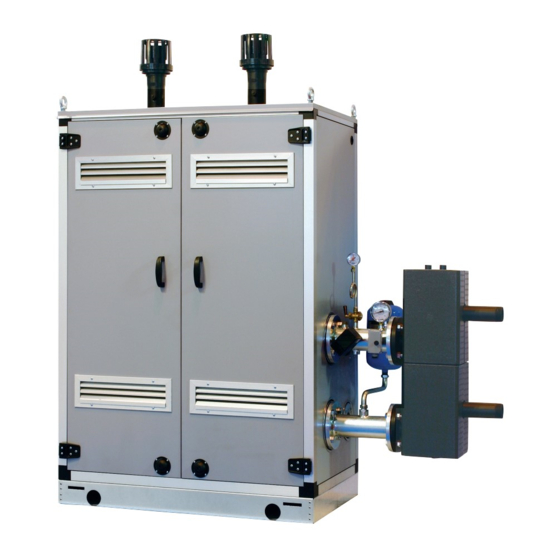
- Page 4 DESCRIPCIÓN DEL APARATO INTRODUCCIÓN sación premezclados, destinados sólo a la cuencia/cascada independientes uno re- calefacción, son acoplables entre ellos y specto a otro. Los módulos térmicos MURELLE EQUI- fácilmente ensamblables, predispuestos PE 140 BOX ErP son aparatos de conden- para el funcionamiento individual o en se- DIMENSIONES MÓDULOS (fig.
- Page 5 DATOS TÉCNICOS MURELLE EQUIPE 140 BOX ErP Generadores con potencia térmica nominal 63,2 kW n° Potencia térmica Nominal (80-60°C) (Pn max) 126,5 Nominal (50-30°C) (Pn max) 136,2 Mínima (80-60°C) (Pn min) 13,4 Mínima (50-30°C) (Pn min) 15,0 Caudal térmico (*) Nominal (Qn max - Qnw max) 130,0 Mínimo (Qn min - Qnw min) 14,0...
- Page 6 ESQUEMA FUNCIONAL (fig. 2) 19 20 LEYENDA 1 Sonda ida de cascada (SMC) 2 Compensador hidráulico 3 ---------- 5 Sifón descarga agua de condensación 6 Válvula gas 7 ---------- 8 Ventilador 9 Sonda ida calefacción (SM) 10 Termostato seguridad 100°C 11 Sonda humos (SF) 12 Intercambiador primario 14 Sonda retorno calefacción (SR)
- Page 7 COMPONENTES PRINCIPALES (fig. 3) Codice/Code 8111235 Modello/Model MURELLE EQUIPE 140 BOX ErP Matricola/Serial n. 9999999999 PAR 1 = 60 (G20) / 62 (G31) PAR 2 = 9 LEGENDA 1 Colector retorno instalación 2 Grifo gas 3 Colector ida instalación 4 Válvula gas 5 Ventilador 6 Termostato seguridad 100°C 7 Sonda ida calefacción (SM)
- Page 8 PLACA DE DATOS TÉCNICOS (fig. 3/a) MODELO TIPO NÚMERO DE MATRÍCULA CÓDIGO AÑO DE CONSTRUCCIÓN NÚMERO PIN DIRECTIVA DE REFERENCIA CONTENIDO DE AGUA CALDERA CAUDAL TÉRMICA MAX CAUDAL TÉRMICA MIN POTENCIA TÉRMICA MAX (80-60°C) POTENCIA TÉRMICA MIN (80-60°C) POTENCIA TÉRMICA MAX (50-30°C) POTENCIA TÉRMICA MIN (50-30°C) MAX PRESIÓN DE SERVICIO TEMPERATURA MAX DE SERVICIO...
- Page 9 INSTALACIÓN La instalación debe considerarse fija y temperatura exterior, ida cascada y cable instalaciones internas o externas, ver los debe ser efectuada exclusivamente por conexiones RS-485 cód. 8092250. A parte puntos 2.6, 2.7 y 2.11 del manual. empresas especializadas y cualificadas, hay disponibles: cumpliendo todas las instrucciones y –...
- Page 10 2.2.2 Al exterior del edificio Sólo las tuberías de plástico de los norma- debe estar conectada con un embudo de les desagües son idóneas para encauzar recolección para encauzar la eventual Los módulos térmicos MURELLE EQUIPE purga en caso de que dicha válvula actúe. el agua de condensación hacia la red de 140 BOX ErP se pueden instalar también ATENCIÓN: No efectuar el lavado de la...
- Page 11 Para este tipo de instalación hacer refe- poner la salida a la izquierda simplemente MURELLE EQUIPE 100 BOX ErP - 140 BOX ErP MURELLE EQUIPE 140 BOX ErP con kit collettore fumi con kit colector de humos cód. 8102511 cod. 8102511 ø...
- Page 12 KIT TUBOS DE CONEXIÓN DEL SEPARADOR HIDRÁULICO (fig. 7) SIME proporciona el kit tubos de conexión del separador hidráulico cód. 8101534 para la instalación con los ataques en el lado izquierdo. El kit tiene la siguiente composición (fig, 7): – Tronco con brida de impulsión instala- ción cód.
- Page 13 2.10 SEPARADOR HIDRÁULICO El separador hidráulico viene suministrado a parte en un kit cód. 8101550 completo de juntas, tuercas y tornillos de fijación (fig. 9). El montaje del separador hidráulico es obligatorio. ATENCIÓN: Es posible introducir el sepa- rador hidráulico en un contenedor de pro- tección cód.
- Page 14 ELÉCTRICA sión monofásica 230V - 50Hz pasando por un interruptor general protegido por fusi- NOTA: La SIME rehúsa cualquier respon- Cada módulo tiene cable eléctrico de ali- bles con distancia entre los contactos de sabilidad ante daños a personas o cosas causados por la falta de conexión a tierra...
- Page 15 2.11.2 Conexión eléctrica de los módulos en secuencia/cascada (fig. 11/a) LEYENDA Línea Neutral Sonda temperatura externa Sonda ida de cascada RS-485 Ficha gestión en cascada NOTA: La sonda de temperatura exterior (SE) se debe conectar a la caldera MASTER y la sonda de impulsión de cascada (SMC) a la caldera SLAVE 1 Las sondas SE, SMC y el cable de conexión de las placas RS-485 se incluyen con los móduos en el kit de sondas cód.
- Page 16 Están Debe ser utilizada exclusivamente con el kit de pro- activas las funciones de protección. gramación de SIME y sólo por personal autorizado. No TECLA MODALIDAD VERANO conectar otros dispositivos electrónicos (cámaras foto- Si se pulsa esta tecla, la caldera funciona sólo gráficas, teléfonos, mp3, etc.).
- Page 17 ACCESO A LA INFORMACIÓN PARA EL INSTALADOR Para acceder a la información para el instalador, pulsar la tecla (3 fig. 12). Cada vez que se pulsa la tecla se pasa a la información siguiente. Si la tecla no se pulsa, el sistema sale automáticamente de la función. Si no está conectada ninguna ficha de expansión (ZONA MIX o SOLAR) no se mostrarán las relativas informaciones.
- Page 18 18. Visualización valor sonda retorno calefacción (SR) 29. Visualización mando de cierre de las válvulas con tarjeta ZONA MIX 2 (respectivamente ON y OFF) 18. Visualizzazione valore sonda ritorno riscaldamento (SR) 29. Visualizzazione comando chiusura valvola con schedino ZONA MIX 2 (rispettivamente ON e OFF) 30.
- Page 19 0 = Inhabilitado La visualización estándar vuelve automáti- 1 = Habilitado camente después de 60 segundos, o al Asignación canales SIME HOME 0 = No asignado pulsar una de las teclas de mando (2 fig. 1 = Circuito 1 2 = Circuito de tres zonas 12) excluido la tecla RESET.
- Page 20 CALDERA PAR 2 PARÁMETROS PARA EL INSTALADOR Instantánea con valv. desviadora e indicador de flujo TARJETA EXPANSIÓN Instantánea con valv. desviadora, indicador de flujo y combinación solar PAR DESCRIPCIÓN RANGO UNIDAD PASO VALOR DE MEDIDA PREDET. Hervidor remoto con Número de tarjetas de expansión 0 ...
- Page 21 El electrodo está conectado a masa o – Interfaz con los siguientes sistemas muy desgastado: es necesario sustituir- electrónicos: control remoto SIME HOME El encendido y la detección de llama se lo. La tarjeta electrónica está averiada. cód. 8092281, termorregulación RVS, controlan por dos electrodos puestos en conexión a una tarjeta de gestión de...
- Page 22 ALTURA DE ELEVACION ción de calefacción está representada, en modulante se ha configurado con un valor DISPONIBLE EN función de la capacidad, del gráfico de la predeterminado (parámetro del instalador LA INSTALACION (fig. 14) fig. 14. PAR 13 = Au). La prevalencia residual para la instala- La velocidad de la bomba instalación WILO PARA 25\9-87 1000...
- Page 23 SIT 848 SIGMA (fig. 16). TRANSFORMACIÓN A OTRO GAS (fig. 17) Esta operación debe necesariamente ser ejecutada por personal autorizado y con componentes originales Sime, so pena de LE YENDA pérdida de vigencia de la garantía. Toma de presión arriba Toma de presión intermedia Entrada señal aire (VENT)
- Page 24 4.5.1 Función deshollinador (fig. 21) Para efectuar la verificación de combustión de la caldera, pulsar unos segundos la tecla para el instalador La función limpiachi- meneas se activa y se mantiene 15 minu- tos. Desde ese momento la caldera empieza a funcionar en calefacción a la máxima potencia, con apagado a 80°C y nuevo encendido a 70°C (ATENCIÓN: Peligro de...
- Page 25 Circuito riscaldamento 3 (impianto tre zone) ANOMALÍAS DE motivo la tarjeta pierde la visibilidad de en el display se visualiza la anomalía ALL FUNCIONAMIENTO la llama, la caldera se para y en el di- 07. Pulsar la tecla del panel de splay aparece la anomalía ALL 06.
- Page 26 Circuito riscaldamento 3 (impianto tre zone) – ANOMALÍA SONDA AUXILIAR “AL 10” intentar el encendido. Durante dicha anomalía la caldera sigue (fig. 23/9) funcionando normalmente. Cuando la sonda anti-hielo sifón (SA) o Apre sonda calentador L.2000 (SB) está abier- – INTERVENCIÓN TERMOSTATO DE SE- GURIDAD SEGUNDA ZONA MEZCLADA ta o en cortocircuito, en el display se vi- “ALL 22”...
- Page 27 ALL 28. Durante dicha anomalía la calde- figuración para instalaciones de 3 zonas. remoto SIME HOME se muestran los códi- ento 2 ra sigue funcionando normalmente pero para la placa solar por la cual es activa gos de error 70 y 71: la anomalía, está...
- Page 28 FALLAS DE FUNCIONAMIENTO DEL CIRCULADOR Cuando ocurre una anomalía de funciona- miento, aparece un LED de color y parpade- ante en la pantalla del circulador. El circu- lador se detiene (según el tipo de anomalía) y hace intentos cíclicos de reiniciarse. A continuación se muestran las descripcio- nes de las anomalías con alarma relativa y solución:...
- Page 29 PARA EL USUARIO ADVERTENCIAS – El aparato puede ser utilizado por niños mayores de 8 años y por personas con capa- cidades físicas, sensoriales o mentales reducidas, o sin la experiencia o los conoci- mientos necesarios, siempre y cuando estén vigilados por una persona responsable, o bien si previamente han sido informados sobre cómo utilizar de forma segura el aparato y han comprendido los peligros relacionados con el mismo.
- Page 30 riscaldamento 3 (impianto tre zone) del panel de mandos (pos. 2). Al pulsarla por primera vez, se seleccio- na el SET del circuito de calefacción 1. Al pulsarla por segunda vez, se seleccio- na el SET del circuito de calefacción 2. Al pulsarla por tercera vez, se selecciona el SET del circuito de calefacción 3 (Tres zonas).
- Page 31 Solicitar la intervención de personal técnico autorizado. – ALL 70 y ALL 71 Estas alarmas se muestran en la pan- talla del mando remoto SIME HOME. Solicitar la intervención de personal técnico autorizado. TRANSFORMACION GAS En el caso que sea necesaria la trans- formación para un gas diferente al que...
- Page 33 FOR THE INSTALLATION TECHNICIAN CONTENTS DEVICE DESCRIPTION ........................page INSTALLATION ............................page FEATURES ............................page USE AND MAINTENANCE ........................page CONFORMITY Our Company declares that MURELLE EQUIPE 140 BOX ErP boilers comply with the essential require- ments of the following directives: - Boiler Efficiency Directive 92/42/EEC - Gas Regulation 2016/426/EC - Electromagnetic Compatibility Directive 2014/30/UE - Low Voltage Directive 2014/35/UE...
- Page 34 DEVICE DESCRIPTION INTRODUCTION mixed condensation heating modules work singularly or in sequence/cascade intended only for heating, inter-connec- autonomously. MURELE EQUIPE 140 BOX ErP are pre- tible and easy to assemble, designed to DIMENSIONS MODULES (fig. 1) MURELLE EQUIPE 100 -140 BOX ErP 1775 1100 FIXTURES...
- Page 35 TECHNICAL SPECIFICATIONS MURELLE EQUIPE 140 BOX ErP Generators with a heat output kW 63.2 n° Heat output Nominal (80-60°C) (Pn max) 126.5 Nominal (50-30°C) (Pn max) 136.2 Minimum (80-60°C) (Pn min) 13.4 Minimum (50-30°C) (Pn min) 15.0 Heat input (*) Nominal (Qn max - Qnw max) 130.0 Minimum (Qn min - Qnw min) 14.0...
- Page 36 OPERATING DIAGRAM 19 20 1 Cascade supply probe (SMC) 2 Hydraulic compensator 3 ---------- 5 Condensation drain siphon 6 Gas valve 7 ---------- 8 Fan 9 Heating supply probe (SM) 10 Safety thermostat 100°C 11 Sensor fumes (SF) 12 Primary exchanger 14 Heating return probe (SR) 15 Pressure transducer 17 Check valve...
- Page 37 MAIN COMPONENTS Codice/Code 8111235 Modello/Model MURELLE EQUIPE 140 BOX ErP Matricola/Serial n. 9999999999 PAR 1 = 60 (G20) / 62 (G31) PAR 2 = 9 1 System return manifold 2 Gas tap 3 System supply manifold 4 Gas valve 5 Fan 6 Safety thermostat 100°C 7 Heating supply probe (SM) 8 Ignition electrode...
- Page 38 TECHNICAL DATA PLATE (fig. 3/a) MODEL TYPE SERIAL NUMBER CODE YEAR OF CONSTRUCTION PIN NUMBER DIRECTIVE OF REFERENCE WATER CONTENT IN BOILER HEAT INPUT MAX HEAT INPUT MIN HEAT OUTPUT MAX (80-60°C) HEAT OUTPUT MIN (80-60°C) HEAT OUTPUT MAX (50-30°C) HEAT OUTPUT MIN (50-30°C) MAX OPERATING PRESSURE MAX OPERATING PRESSURE...
- Page 39 2.2.2 Outdoors Current regulations must also be met. ors) code 8102511 MURELLE EQUIPE 140 BOX ErP heat modu- – Exhaust terminal code 8089530 for outdoor installations. les can also be installed outdoors with the SUPPLY (fig. 4)
- Page 40 For long-term protection agains corrosion demand, limiting pressure loss between to entrap all the impurities in the gas or in and deposits, the use of inhibitors such as the meter and any utility device no greater gas main pipes. Sentinel X100 or Fernox Protector F1 is than 1.0 mbar for second family gas (natu- To prevent malfunctioning of the valve, or recommended after cleaning the system.
- Page 41 Refer to fig. 6 for this type of installation. of the left by simply rotating the manifold ors. MURELLE EQUIPE 100 BOX ErP - 140 BOX ErP MURELLE EQUIPE 140 BOX ErP con kit collettore fumi exhaust manifold kit code 8102511 cod. 8102511 ø 160...
- Page 42 TUBES CONNECTING THE HYDRAULIC SEPARATOR KIT (fig. 7) SIME provides the tubes connecting the hydraulic separator kit code 8101534 for in- stallations with left-hand side attachments. The kit is made up of the following compo- nents (fig. 7): – System supply flanged section code 6291965 –...
- Page 43 2.10 HYDRAULIC SEPARATOR (fig. 9) The hydraulic separator is supplied sepa- rately in a kit code 8101550 complete with gaskets, nuts and fastening screws (figure 9). The compensator is required in the assembly. WARNING: The hydraulic separator can be inserted in a specific protective box code 8101517 supplied separately.
- Page 44 CONNECTIONS 230V – 50 Hz single phase voltage is requi- red using a fuse protected main switch NOTE: SIME shall not be liable for any Each module is supplied with a power cord with at least 3 mm. between contacts.
- Page 45 2.11.2 Electrical connection of modules in sequence/cascade (fig. 11/a) Line Neutral External sensor Cascade supply probe RS-485 Cascade management board NOTICE: The external temperature probe (SE) must be connected to the MASTER boiler and the cascade supply probe (SMC) to the SLAVE 1 boiler. The SE, SMC probes and the RS-485 board connection cable are supplied together with the modules in the probe kit code 8092250.
- Page 46 PC CONNECTION OFF = Electricity supply to boiler is on but nor To be used only with the SIME programming kit and only ready for functioning. However, the protec- by authorised personnel. Do not connect other electro- tion functions are active.
- Page 47 ACCESS TO INSTALLER’S INFORMATION For access to information for the installer, press the key (3 fig. 14). Every time the key is pressed, the display moves to the next item of information. If the key is not pressed, the system automatically quits the function. If there is no expansion board (ZONA MIX or SOLAR) the relative info shall not be displayed.
- Page 48 18. Visualisation C.H. return sensor value (SR) 29. Visualisation valve closing opening control with board ZONA MIX 18. Visualizzazione valore sonda ritorno riscaldamento (SR) 29. Visualizzazione comando chiusura valvola con schedino 2 (respectively ON and OFF) ZONA MIX 2 (rispettivamente ON e OFF) 30.
- Page 49 The standard visualisation returns automa- of voltage 1 = Enabled tically after 60 seconds, or by pressing one Allocation of SIME HOME channels 0 = Not assigned 1 = Circuit 1 of the control keys (2 fig. 12) excluded the 2 = Three-zone circuit key RESET.
- Page 50 BOILER PAR 2 PARAMETERS INSTALLER Instant with deviator valve and flowmeter EXPANSION CARD Instant with deviator valve, flowmeter and solar combination PAR DESCRIPTION RANGE UNIT OF INC/DEC DEFAULT MEASUREMENT UNIT SETTING D.H.W. tank with Number of expansion boards 0 ... 3 deviator valve and boiler sensor Mix valve stroke time 0 ...
- Page 51 In the boiler, only the opening of the gas – Interface with the following electronic to the burner can be detected. After 10 systems: remote control SIME HOME ELECTRONIC IGNITION seconds the anomaly is signalled. It can code 8092281, thermal regulator RVS,...
- Page 52 HEAD AVAILABLE graph in fig. 14. TO SYSTEM (fig. 14) The speed of the modulating pump system is set as default (installation parameter Residual head for the heating system is PAR 13 = Au). shown as a function of rate of flow in the WILO PARA 25\9-87 1000 1200...
- Page 53 GAS VALVE (fig. 16) The boiler is supplied as standard with a gas valve, model SIT 822 NOVAMIX (fig. 16). GAS CONVERSION (fig. 17) This operation must be performed by authorised personnel using original Sime components. 4.2.1 New fuel configuration Upstream pressure intake Intermediate pressure intake For access to the installer’s parameters,...
- Page 54 4.5.1 Chimney sweep function (fig. 21) To check boiler combustion, press the installer’s key for a few seconds. The chimney sweep function will switch on and will continue for 15 minutes. From that moment, the boiler will start wor- king in heating mode at maximum power, with cut off at 80°C and re-ignition at 70°C (ATTENTION! Temperature may reach excessive values when using unprotected...
- Page 55 FUNCTIONING ANOMALIES Apre When there is a functioning anomaly, an Circuito Circuito alarm appears on the display and the blue riscaldamento 2 riscaldamento 2 luminous bar becomes red. Descriptions of the anomalies with relative alarms and solutions are given below: Circuito riscaldamento 2 –...
- Page 56 Apre – SAFETY/LIMIT THERMOSTAT ANOMALY ALARM 07 (fig. 23/6) If the connection with the safety thermo- Circuito stat/limit thermostat is interrupted, the riscaldamento 2 boiler will stop; the flame control will remain waiting to be switched off for one minute, keeping the system pump on for that period.
- Page 57 (impianto tre zone) – “ALL 15” FAN ERROR (fig. 23/12) – SAFETY THERMOSTAT INTERVENTION – AUXILIARY SENSOR ANOMALY (S3) rcuito scaldamento 2 Circuito SECOND MIXED ZONE “ALL 22” (fig. “ALL 26” (fig. 23/20) The fan speed does not fall within the ra- riscaldamento 2 ted speed range.
- Page 58 CAUTION: In the event of sequence/casca- splayed. de connection, error codes 70 and 71 will The boiler restarts when the boiler three- zone system configuration is activated appear on the SIME HOME remote control display: - ALARM 70 When an anomaly affects cascade ope- Circuito...
- Page 59 CIRCULATOR OPERATION FAULTS When an operating anomaly occurs, a co- lored and flashing LED appears on the circulator display. The circulator stops (depending on the type of anomaly) and makes cyclical attempts to restart. Below are the descriptions of the anomalies with relative alarm and solution: ANOMALY CAUSE...
- Page 60 USER INSTRUCTIONS WARNINGS – The appliance can be used by children under 8 years and by persons with reduced physical, sensory or mental capabilities, or lack of experience or knowledge, provided they are un- der supervision or after they have been given instructions concerning the safe handling of the appliance and the understanding of the dangers inherent to it.
- Page 61 Request assistance from qualified tech- zone) zone) nical personnel. Circuito riscaldamento 2 – ALL 70 and ALL 71 These alarms appear on the SIME HOME remote control display. Request assi- stance from qualified technical person- Circuito riscaldamento 3 Fig. 27/d Fig. 27/a nel.
- Page 62 GAS CONVERSION If it is necessary to change to a different type of gas, request assistance only from authorised technical personnel. MAINTENANCE Annual maintenance of the appliance should be planned sufficiently in advance, requesting the assistance of authorised technical personnel. ATTENTION: It is mandatory that the ded- icated power cable is replaced only with a spare cable ordered and connected by...
- Page 63 APPENDIX DETALLES DEL PRODUCTO / PRODUCT DETAILS Murelle 70 BOX ErP Murelle Equipe 140 BOX ErP Classe efficienza energetica stagionale riscaldamento Clase de eficiencia energética estacional en calefacción Classe de eficiência energética do aquecimento ambiente sazonal C.H. energy efficiency class Potenza termica (kW) Potencia térmica (kW)
- Page 64 Daily electricity consumption Recapiti / Datos de contacto Fonderie Sime S.p.A. Via Garbo 27, 37045 Legnago (VR) ITALIA Elementos de contacto / Contact details a. Regime ad alta temperatura: temperatura di ritorno di 60°C all’entrata e 80°C di temperatura di fruizione all’uscita dell’apparecchio b.
- Page 65 NOTES...
- Page 66 NOTES...
- Page 68 Fonderie Sime S.p.A - Via Garbo, 27 - 37045 Legnago (Vr) Tel. +39 0442 631111 - Fax +39 0442 631292 - www.sime.it...
Need help?
Do you have a question about the MURELLE EQUIPE 140 BOX ErP and is the answer not in the manual?
Questions and answers