Table of Contents
Advertisement
Advertisement
Table of Contents

Related Manuals for UNI-T UTG4000A


Summary of Contents for UNI-T UTG4000A
- Page 1 UTG4000A Quick Guide Function/Arbitrary Waveform Generator...
- Page 2 UTG4000A Operating Manual Introduction Dear Users: Hello! Thank you for choosing this brand new UNI-T device. In order to safely and correctly use this instrument, please read this manual thoroughly, especially the Safety Notes part. After reading this manual, it is recommended to keep the manual at an easily...
- Page 3 Document Version UTG4000A-20160618-EN-V1.2 Statement ● UNI-T products are protected by patent rights in China and foreign countries, including issued and pending patents. ● UNI-T reserves the rights to any product specification and pricing changes. ● UNI-T reserves all rights. Licensed software products are properties of Uni-Trend and its subsidiaries or suppliers, which are protected by national copyright laws and international treaty provisions.
- Page 4 UNI-T, pay the shipping cost, and provide a copy of the purchase receipt of the original purchaser. If the product is shipped domestically to the location of the UNI-T service center, UNI-T shall pay the return shipping fee.
-
Page 5: Table Of Contents
UTG4000A Operating Manual Table of Contents Chapter 1 Safety Information -------------------------------------------------------------------------5 1.1 Safety Terms and Symbols ----------------------------------------------------------------5 1.2 General Safety Overview ----------------------------------------------------------------6 Chapter 2 Quick Start -----------------------------------------------------------------------------------7 2.1 General Inspection---------------------------------------------------------------------------7 2.1.1 Inspect Whether Damage is Caused by Transportation -------------------7 2.1.2 Inspect Accessories ----------------------------------------------------------------7 2.1.3 Inspect Complete Machine -------------------------------------------------------7... -
Page 6: Chapter 1 Safety Information
UTG4000A Operating Manual Chapter 1 Safety Information 1.1 Safety Terms and Symbols The following terms may appear in this quick guide: Warning: The conditions and behaviors may endanger life. Caution: The conditions and behaviors may cause damage to the product and other properties. -
Page 7: General Safety Overview
UTG4000A Operating Manual 1.2 General Safety Overview This instrument is designed and produced in strict accordance with GB4793 Safety Requirements for Electronic Measuring Apparatus and IEC61010-1 safety standard, up to insulation and overvoltage standard CAT II 300V and safety standard for level-II pollution. -
Page 8: Chapter 2 Quick Start
2.1.2 Inspect Accessories UTG4000A accessories include power line (applicable to the destination country/region), a USB data transmission line, two BNC cables (1m), a user CD and a product warranty card. -
Page 9: Function Interface
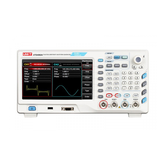
UTG4000A Operating Manual Figure 2-1 Structure of front panel 2.2.3 Function Interface Function interface is shown in Figure 2-2: Soft Waveform labels parameter list Waveform display area Figure 2- 2 Function interface... -
Page 10: Back Panel
UTG4000A Operating Manual 2.2.4 Back Panel Back panel is shown in Figure 2-3: Figure 2-3 Structure of back panel 2.3.1 Output Basic Waveform 2.3.2 Set Output Frequency The default configuration of waveform is a sine wave with frequency of 1kHz and peak-to-peak amplitude of 100mV (terminating at 50Ω) when powering on. - Page 11 UTG4000A Operating Manual Figure 2- 4 Setting of selected frequency 2. Input the required number 2.5 with numeric keyboard. The left direction key can be used as backspace during input. Figure 2- 5 Set frequency 3. Select required unit Press soft key of corresponding unit. The waveform generator outputs waveform with the displayed frequency when you select unit (if output has been used).
-
Page 12: Set Output Amplitude
UTG4000A Operating Manual 4. Use multi-functional knob and direction key for parameter setting In default state, rotate multi-functional knob to switch between multiple soft keys of function menu. When setting some parameter, press the multi-functional knob to select a bit of the parameter after selecting the corresponding parameter, when the parameter bit is highlighted in blue. -
Page 13: Set Dc Offset Voltage
UTG4000A Operating Manual 2.3.4 Set DC Offset Voltage The default configuration of waveform is a sine wave with DC offset voltage of 0V (terminating at 50Ω) when powering on. The specific steps for changing DC offset voltage into -150mV are as follows: 1. -
Page 14: Set Pulse Wave
50% threshold value of the next falling edge in each cycle (suppose waveform is not reversed). You can conduct parameter configuration for UTG4000A function/arbitrary waveform generator to output pulse waveform with variable pulse width and edge time. The default duty ratio of pulse wave is 50% when powering on. -
Page 15: Frequency Measurement
UTG4000A Operating Manual 2.4 Frequency Measurement This function/arbitrary waveform generator can measure frequency and duty ratio of compatible TTL level signal. The range of frequency measurement is 100mHz~200MHz. When frequency meter is used, signal of compatible TTL level is input through external frequency meter interface (Counter connector). -
Page 16: Chapter 3 Advanced Applications
Press MOD, Type and AM to use AM function (if Type is not highlighted, press soft key Type to select). After AM function is used, UTG4000A function/arbitrary waveform generator will output modulated waveform with the current modulation waveform and carrier wave. - Page 17 Select modulation source UTG4000A function/arbitrary waveform generator can selected as internal or external modulation source. After you use AM function, you can see that modulation source is internal by default. You can change it with multi-functional knob on AM interface or by...
- Page 18 UTG4000A Operating Manual Figure 3- 3 Select modulation source 1) Internal source In case of internal modulation source, modulation wave can be sine wave, square wave, oblique wave, or arbitrary wave, and is sine wave by default. After you use AM function, you can see that modulation wave is sine wave by default.
- Page 19 UTG4000A Operating Manual Set modulation wave frequency The frequency of modulation wave can be set in case of internal modulation source. After you use AM function, you can see that frequency of modulation wave is 100Hz by default. You can change it with multi-functional knob and direction key on AM interface or by pressing Freq.
- Page 20 UTG4000A Operating Manual Figure 3-4 Select AM function 2) Set modulation signal parameters Set with multi-functional knob and direction key after using AM function. You can also press soft keys of function on the above interface for using AM function.
- Page 21 UTG4000A Operating Manual Figure 3-6 Set frequency of modulation source 3) Set carrier signal parameters Select type of basic waveform in modulation mode. Press Square to select carrier signal as square wave. Figure 3-7 Set carrier frequency You can set with multi-functional knob and direction key, or press corresponding soft...
- Page 22 UTG4000A Operating Manual Figure 3-8 Select carrier duty ratio To set parameters, press corresponding soft key, input the required value and select the unit. Figure 3-9 Set carrier duty ratio 4) Set modulation depth Press soft key MOD to return to the interface below to set modulation depth after...
- Page 23 UTG4000A Operating Manual Figure 4- 10 Select modulation depth You can set with multi-functional knob and direction key. You can also press soft key Depth again, input number 80 through numeric keyboard and press soft key % to set the modulation depth.
- Page 24 UTG4000A Operating Manual 5) Use channel output Press CH1 on the front panel to quickly turn on output of channel 1. Backlight of CH1 is on after channel output is turned on, “OFF” on the right of CH1 information tag turns gray from white, and “ON”...
-
Page 25: Output Arbitrary Wave
U disk through USB interface of front panel and outputs arbitrary wave. 3.2.1 Use Arbitrary Wave Function Press Arb to use arbitrary wave function. After the function is used, UTG4000A function/arbitrary waveform generator will output arbitrary waveform with the current setting. Figure 3-14 Select Arb function 3.2.2... -
Page 26: Select Arbitrary Wave
Note: use multi-functional knob and direction key or press soft keys Arb and Wave successively to select storage after inserting U disk into USB interface of front panel, and then select the arbitrary waveform you need. UTG4000A supports *.csv or *.bsv files with waveform 8~32M points long. - Page 27 UTG4000A Operating Manual Digital interface 数字接口 Connecting plug 连接插头 Tap 1 Tap 2 分接头1 分接头2 See the table below for correspondence of signal Table 3- 1 Pin name Function description Ground pin RS232_TXD, serial data sending SPI_CS,SPI enable SPI_SDO,SPI data sending end SPI_CLK,SPI clock...
- Page 28 Select UART Press DIGITAL, Type and Uart successively to use UART function (if Type is not highlighted, press soft key Type to select). After UART function is used, UTG4000A function/arbitrary waveform generator will output protocol signal with the current setting.
- Page 29 Figure 3- 18 Set bit Set data sent UTG4000A function/arbitrary waveform generator can set protocol data coding to be sent. After you use UART function, you can see that data is empty by default. You can set with...
- Page 30 UTG4000A Operating Manual multi-functional knob on interface for using protocol function or by pressing Data. The data can be sent with multiple numerical systems, including decimal system, hexadecimal system and character, as shown in the figure below. Figure 3- 19 Set data sent Multibyte sending can be set.
- Page 31 UTG4000A Operating Manual Set sending mode Automatic and manual sending can be set. In the state of automatic sending, the instrument sends the set protocol coding in certain time; in manual mode, the instrument sends the set protocol signal when users press the send key.
- Page 32 UTG4000A Operating Manual Figure 3- 22 Set manual sending Set stop bit Different stop bit width can be set in UART protocol. Press soft function key Stop Bit to set different stop bit width, which can be 1 or 2 and is 1 by default.
- Page 33 UTG4000A Operating Manual Set check bit Check mode can be set in UART protocol. Press soft function key Parity to set different check mode, which can be no, odd and even and is no by default. Figure 3- 24 Set check bit...
- Page 34 UTG4000A Operating Manual Figure 3- 25 Select UART function 2) Set Baud rate to be 4800 Press soft function key Baud Rate to set Baud rate in UART mode. You can set with multi-functional knob and direction key. You can also press corresponding soft function keys again, when the interface below will pop up.
- Page 35 UTG4000A Operating Manual Figure 3- 27 Select bit 4) Set data sent Press soft function key Data for data setting in UART mode. You can set with multi-functional knob and direction key. You can also press corresponding soft function keys again, when the interface below will pop up.
- Page 36 UTG4000A Operating Manual Figure 3- 29 Set send time 6) Set stop bit Press soft function key Stop Bit to set sending mode and set stop bit to be 1 in UART mode. Figure 3- 30 Set stop bit 7) Set check bit...
-
Page 37: Function Of Digital Arbitrary Wave
Press DIGITAL, Type and DArb successively to use function of digital arbitrary wave (if Type is not highlighted, press soft key Type to select). After function of digital arbitrary wave is used, UTG4000A function/arbitrary waveform generator will output signal of digital arbitrary wave with the current setting. - Page 38 UTG4000A Operating Manual Figure 3- 32 Select function of digital arbitrary wave Set Clock The sending clock of digital arbitrary wave can be set as required by users. Press function key Clock in mode of digital arbitrary wave to set sending clock with numeric key in the range of 1kHz~40MHz.
- Page 39 UTG4000A Operating Manual Set data sent Different bit number can be set as required. Set with multi-functional knob and direction key after selecting protocol or by pressing soft function key Data and using numeric key. The data can be sent with multiple numerical systems, including decimal system, hexadecimal system and character, which is shown in the figure below.
- Page 40 UTG4000A Operating Manual Figure 3- 35 Set data sent Set sending mode Automatic and manual sending can be set. In the state of automatic sending, the instrument sends the set protocol coding in certain time; in manual mode, the instrument sends the set protocol signal when users press the send key.
- Page 41 UTG4000A Operating Manual 2) Manual sending mode Press soft function key SendMode to adjust to “Manual” to set manual sending mode of the instrument. Press soft function key Send, the instrument will output the set waveform. Figure 3- 37 Set manual sending...
- Page 42 UTG4000A Operating Manual Figure 3- 38 Select function of digital arbitrary wave 2) Set Clock Press soft function key Clock for data setting in mode of digital arbitrary wave. You can set with multi-functional knob and direction key. You can also press corresponding soft function keys again and set corresponding data to be 200kHZ with numeric key.
- Page 43 UTG4000A Operating Manual Figure 3- 40 Set data sent 4) Set sending mode Press soft function key Send Mode in digital arbitrary wave mode to set sending mode to be “Continue”. Figure 3- 41 Set sending mode...
-
Page 44: Chapter 4 Fault Handling
UTG4000A Operating Manual Chapter 4 Fault Handling Possible faults in use of UTG4000A and troubleshooting methods are listed below. If these faults occur, please handle them according to corresponding steps. If they cannot be handled, please contact with the dealer or local office, and provide the information about your machine (method: press Utility and System successively). - Page 45 UTG4000A Operating Manual This user manual may be revised without prior notice...
- Page 46 UTG4000A Operating Manual...
- Page 47 REV.0 DATE:2016/06/30...
- Page 48 说明书菲林做货要求: 序号 项目 内容 尺寸210*297MM±1MM 尺寸 材质 颜色 黑色,双面印刷 外观要求 印刷完整清晰、版面整洁,无斑墨、残损、毛边、刀线错位等缺陷 胶装 装订方式 无 表面处理 折叠方式 无 版本 Part NO. 武广英16/06/30 MODEL 设 计 物料编号: 机型: UTG4000A系列说明书 审 核 APPRO. 批 准 Remark:不需要印刷在说明书中...
Need help?
Do you have a question about the UTG4000A and is the answer not in the manual?
Questions and answers