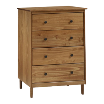
Walker Edison BR4DDR Assembly Instructions Manual
Hide thumbs
Also See for BR4DDR:
- Assembly instructions manual (11 pages) ,
- Assembly instructions manual (10 pages)
Summary of Contents for Walker Edison BR4DDR
- Page 1 BR4DDR Assembly Instructions Please visit our website for the most current instructions, assembly tips, to report damage or request parts. www.walkeredson.com ® Revised 07/2020 Copyright © 2018, by Walker Edson Furniture Co., LLC, All rights reserved.
-
Page 3: Warning Label
The side drawer with WARNING LABEL, should be mouted in highest drawer. Part# Description Part# Description Top panel 01 pcs Drawer runner 08 pcs Right side panel 01 pcs Front drawer 04 pcs Left side panel 01 pcs Left side drawer 04 pcs Bottom front crossbeam 01 pcs... - Page 4 Wooden dowel Ø8*30mm Ø8*20mm Wooden dowel Screw Ø3,5*25mm Ø3,5*30mm Screw M4*22mm Screw Ø4,5*45mm Screw Nail Ø10*10 Knob Glue 540 mm “H” Profile Wall anchor Washer Ø6mm Ø7*80mm Screw Allen key Screw Ø3,5*16mm Hammer recommended for assembly (not included)
- Page 5 Step 1 Ø8*30mm Insert wood dowel (A) and glue (I) into parts (2, 3, 4, 5, 6, 11, 12). Ø8*20mm Insert wood dowel (B) and glue (I) into part (9). Step 2 Use screw (C) to atach parts (2,3) to part (9) Ø3,5*25mm...
- Page 6 Step 3 Secure front cross beam (4,5,6) to panels (2,3) using screw (D) Ø3,5*30mm Step 4 Use screw (D) to atach part (1) to body Ø3,5*30mm...
- Page 7 Step 5 Please assemble on a clean soft surface to avoid damage. Use screw (D) to atach part (6) to body Ø3,5*30mm Step 6 Apply glue to leg contact surfaces Use screw (N) to atach part (17) to part (8) and key (0).
- Page 8 Step 7 Ø3,5*30mm Secure an - pping (23) using s ew (D) (P) Ø3,5*16mm Step 8 Ø10*10 Secure back panel (7) with part (J) to body with nails (G) 540mm...
- Page 9 Step 9 Insert wood dowel (A) into part (9) (Runner small). FRONT Ø8*30mm Step 10 Atach parts (11,12) to part (10), insert panel (13) into groves and secure part (14) with screws(D) Insert knob (H) with screws(E). Ø3,5*30mm M4x22mm...
- Page 10 Step 11 s dra side to be d in IN G t dra ·In ·Pl ll tipo ·Do this Tv’ item ·Ne cifi s or s in allo ly des t,un ·Ne rs,d w chi s the ldre ·Do n mo n to t is s on...
-
Page 11: Back Panel
Wall anchor and hardware are included with this product. Please make sure hardware is suitable for your walls before installing, as different wall materials may require different types of anchors. 1º 2º Wall Back panel Ø6mm Ø3,5*30mm P.11...


Need help?
Do you have a question about the BR4DDR and is the answer not in the manual?
Questions and answers