Table of Contents
Advertisement
Quick Links
Description:
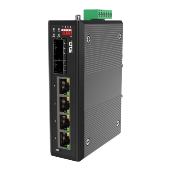
Hardened Grade Lite-managed 4-port 10/100/1000Base-TX (PoE++) + 2-port
1000Base- SFP Ethernet Switch
Overview:
ET4222Pp9H-S-DR is a DIN rail type media converter that supports external SFP. It is a
Hardened grade product whose operating temperature range is -40 ℃ to 75 ℃ .
ET4222Pp9H-S-DR supports 10/100/1000M Ethernet port and 1000M SFP port. The
Ethernet port supports both half-duplex and full-duplex mode. Users can use different
type of SFP modules (single-mode/multi-mode fiber, 1/2 core) as needed.
Package Content
⚫
Lite-managed PoE Switch x 1
⚫
Caps, plastic, for SFP or SC or ST fiber port Slots x 2
⚫
Wall-Mount Kits x 2
⚫
DIN-Rail Clip x 1
⚫
Quick Start Guide x 1
◎
Keep power off during installation
◎
use Antistatic Wrist Strap correctly
Quick Installation Guide
ET4222Pp9H-S-DR
Read Before Install
Quick Installation Guide
ET4222Pp9H-S-DR/ version 3.0
OT Systems Ltd. | www.ot-systems.com
Advertisement
Table of Contents

Related Manuals for OTS ET4222Pp9H-S-DR


Summary of Contents for OTS ET4222Pp9H-S-DR
- Page 1 1000Base- SFP Ethernet Switch Overview: ET4222Pp9H-S-DR is a DIN rail type media converter that supports external SFP. It is a Hardened grade product whose operating temperature range is -40 ℃ to 75 ℃ . ET4222Pp9H-S-DR supports 10/100/1000M Ethernet port and 1000M SFP port. The Ethernet port supports both half-duplex and full-duplex mode.
- Page 2 Quick Installation Guide ET4222Pp9H-S-DR/ version 3.0 ◎ Make sure using correct power supply, voltage must match ◎ Make sure enough power supply from PSU that will not overload ◎ Double check the wiring ( +/- ) is correct. ◎ Keep installation dry and clean.
- Page 3 Quick Installation Guide ET4222Pp9H-S-DR/ version 3.0 b) Insert the appropriate SFP into the SFP port. Connect the fiber cable from the device (media converter or switch) on the other end to the LC connector of the SFP. c) After the device is powered on, the PWR indicator will all be on. If the indicators are not on, check the power supply connection.
Need help?
Do you have a question about the ET4222Pp9H-S-DR and is the answer not in the manual?
Questions and answers