Advertisement
Quick Links
Quick Start Guide
25.6T Data Center Switch
AS9736-64D
1
1.
25.6T Data Center Switch AS9736-64D
2.
Rack mounting kit—2 front-post brackets, 2 rear-post brackets
and 24 screws
1
2
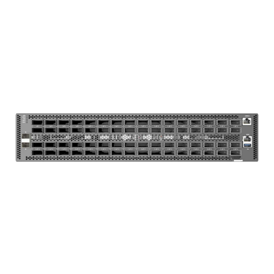
1.
System LEDs
2.
2 x 10G SFP+ management ports
3.
64 x 400G QSFP56-DD ports
4.
RJ-45 console port
5.
1000BASE-T RJ-45 management port, USB
1.
System LEDs
LOC: Flashing Blue/Amber (switch locator)
STAT: Green (OK), Blinking Green (system booting), Amber (fault)
FAN: Green (OK), Amber (fault), Blinking Amber (too few fans
installed)
PSU1/PSU2: Green (OK), Amber (fault)
2.
SFP+ 10G LEDs: Left: Green (10G link), Amber (1G link)
Right: Green (10G activity), Amber (1G activity)
3.
RJ-45 MGMT LEDs:
Left: Green (1G link), Amber (10/100M link)
Right: Green (1G activity), Amber (10/100M activity)
PSU 1
PSU Replacement
1.
Remove the power cord.
2.
Press the release latch and remove the PSU.
3.
Install the replacement PSU in a matching orientation.
(PSU 1 AC socket faces down, and PSU 2 AC socket faces up.)
Package Contents
3
System/Port LEDs
1
FRU Replacement
PSU 2
2
3.
HVAC/IEC C20 1m power cord
4.
Documentation—Quick Start Guide (this document) and Safety
and Regulatory Information
Overview
4
6
5
7
6.
PSU 1
7.
2 x grounding screws (maximum torque 10 kgf-cm (8.7 lb-in)
8.
4 x fan trays
9.
PSU 2
2
4
4.
QSFP56-DD LEDs
400G (1 x 8 lanes 50G PAM4): 1 LED Blue
200G (2 x 4 lanes 50G PAM4): 2 LEDs Cyan
100G (4 x 2 lanes 50G PAM4): 4 LEDs Green
100G (1 x 4 lanes 25G NRZ): 1 LED Green
40G (1 x 4 lanes 10G NRZ): 1 LED Dark Green
50G (2 x 2 lanes 25G NRZ): 2 LEDs Red
25G (4 x 1 lane 25G NRZ): 4 LEDs Orange
10G (4 x 1 lane 10G NRZ): 4 LEDs Yellow
Fan Tray Replacement
1.
Pull the handle release latch.
2.
Remove fan tray from the chassis.
3.
Install replacement fan with matching airflow direction.
– 1 –
www.edge-core.com
3
4
8
7
3
3
E042023-CS-R02
150200002542A
9
Advertisement

Subscribe to Our Youtube Channel
Related Manuals for Edge-Core DCS520


Summary of Contents for Edge-Core DCS520
- Page 1 Quick Start Guide 25.6T Data Center Switch www.edge-core.com AS9736-64D Package Contents 25.6T Data Center Switch AS9736-64D HVAC/IEC C20 1m power cord Rack mounting kit—2 front-post brackets, 2 rear-post brackets Documentation—Quick Start Guide (this document) and Safety and 24 screws and Regulatory Information...
- Page 2 Verify Rack Ground Information about compatible software can be found at Ensure the rack on which the device is to be mounted is properly www.edge-core.com grounded and in compliance with ETSI ETS 300 253. Verify that there is Note: The drawings in this document are for illustration only a good electrical connection to the grounding point on the rack (no and may not match your particular model.
- Page 3 Quick Start Guide Make Management Connections Hardware Specifications Size (WxDxH) 440 x 649.2 x 87 mm (17.32 x 25.56 x 3.43 in.) Weight 21.5 kg (47.4 lb), with 2 PSUs and 4 fans installed Temperature Operating: 0° C to 45° C (32° F to 113° F) Storage: -40°...
Need help?
Do you have a question about the DCS520 and is the answer not in the manual?
Questions and answers