
Related Manuals for Kyoritsu Electrical Instruments Works KEW 3124A


Summary of Contents for Kyoritsu Electrical Instruments Works KEW 3124A
- Page 1 INSTRUCTION MANUAL HIGH VOLTAGE INSULATION TESTER KEW 3124A GlobalTestSupply www. .com Find Quality Products Online at: sales@GlobalTestSupply.com...
-
Page 2: Table Of Contents
CONTENTS 1. SAFETY WARNINGS ···································································· 1 2. FEATURES ················································································· 4 3. SPECIFICATIONS ········································································ 5 4. INSTRUMENT LAYOUT ································································ 9 5. PREPARATIONS FOR TESTS ······················································ 10 6. OPERATING INSTRUCTIONS ······················································ 12 7. BATTERY CHARGING ································································ 17 8. BATTERY REFRESH ·································································· 20 9. -
Page 3: Safety Warnings
1. SAFETY WARNINGS ○ T his instruction manual contains warnings and safety rules which must be observed by the user to ensure safe operation of the instrument and to maintain it in safe condition. Therefore, read through these operating instructions before using the instrument. # DANGER ● R ead through and understand instructions contained in this manual before starting to use the instrument. - Page 4 # DANGER ● D o not attempt to make measurements in the presence of flammable gasses. Otherwise, the use of the instrument may cause sparking, which can lead to an explosion. ●Never attempt to use the instrument if its surface or your hand is wet. ● T his insulation tester will produce a high DC Voltage of 10kV. Do not press the Test button when connecting the test leads to the equipment (circuit) under test. ●Never open the battery compartment cover during a measurement. ● T o prevent possible electrical shock, do not touch the circuit under test during an insulation resistance measurement or right after a measurement.
- Page 5 # CAUTION ● B efore starting a measurement, confirm that the Function switch is at an appropriate position. ● S et the Function switch to OFF position after use. R emove the batteries if the instrument is to be stored and will not be in use for a long period. ● D o not expose the instrument to direct sunlight, high temperature and humidity or dew. ● U se a damp cloth with alcohol for cleaning the areas around the measuring terminals. ●When this instrument is wet, please store it after it dries. ● W ait for a while until the voltage indicator shows 0 V, before disconnecting ...
-
Page 6: Features
2. FEATURES ● S uited for heavy duty electrical maintenance and servicing of industrial installations, cables, transformers, generators and switchgears where high voltage insulation tests are required. ● M easures high voltage insulation resistance up to 100GΩ at a variable voltage between 1kV and 10kV. ● T he digital display indicates set voltage at 100GΩ and output voltage. After ... -
Page 7: Specifications
3. SPECIFICATIONS ● High Voltage Range at Variable Test Voltage Nominal Test Voltage 1kV-10kV/DC (Variable) 0-1.6GΩ/1-100GΩ Measuring Range (Auto ranging) 0.05-50GΩ ±10% of rdg ±1 % of scale length Insulation (When test voltage is below Resistance Other Ranges Accuracy 2kV, the accuracy is not guaranteed at 50-100GΩ) Output ±2% of set value ±2dgt Voltage (on Open Circuit) ● 1kV/ 100MΩ Range Nominal Test Voltage Measuring Range 0-100MΩ 1-100MΩ ±10% of rdg Insulation Resistance Other Ranges ±1 % of scale length Accuracy Open Circuit 1kV ±10%... - Page 8 Current Consumption: 80mA approx. in stand-by state, 300mA max. in operation Battery Alarm: As battery voltage lowers, the illuminating Battery Alarm (BATT. ALARM) alternates its colour to Green, Yellow and Red. Threshold voltages between Green and Yellow, and Yellow and Red are approximately 9.6V and 9.1V respectively. Y ellow shows that batteries need to be charged and Red indicates that the instrument is going inoperative.
- Page 9 Power Source: Eight Ni-MH rechargeable AA size batteries, HR15/51 (1) Ratings Rated capacity min. 1900mAh (at discharge rate 0.1CmA) Nominal voltage 1.2V (2) Charge conditions See section 7 for Battery charging. (3) Storage conditions A t a temperature of -20℃ to +30℃ and low humidity, where there are no corrosive gasses (4) Battery life T he number of tests is not less than 500, under appropriate charge, discharge and storage conditions. W hen the number of tests per one charge largely ...
- Page 10 KEW3124A GlobalTestSupply www. .com Find Quality Products Online at: sales@GlobalTestSupply.com...
-
Page 11: Instrument Layout
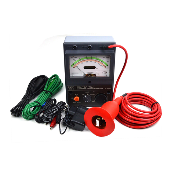
4. INSTRUMENT LAYOUT ①Line Probe ⑪Output Voltage ②Guard Terminal and Set Voltage Indicator ③Earth Terminal ⑫Meter Movement Zero Adjust ④Battery Alarm ⑬Terminal for Battery Charging ⑤Battery Charging Indicator ⑭Output Terminal for Recorder ⑥High Scale ⑮Test Button ⑦Low Scale ⑯Function Switch ⑧1kV/ 100MΩ Scale ⑰Output Voltage Set Knob ⑨High Scale Indicator ⑱Earth Lead (Black) ⑩Low Scale Indicator ⑲Guard Lead (Green) ③ ② ④ ⑤ ⑥ ⑦ ⑧ ⑨... -
Page 12: Preparations For Tests
5. PREPARATIONS FOR TESTS 5-1 Mechanical Zero Adjustment W ith the Function switch set to the OFF position, check the meter pointer lines up with the "∞" mark on the scale. If not, adjust it by rotating the Meter Movement Zero Adjust with a small screwdriver. 5-2 Test leads connection C onnect the Earth lead (black) to the Earth Terminal of the instrument. If necessary, connect the Guard lead (green) to the Guard Terminal of the instrument. (See section 6-3 for How to use the Guard terminal. ) 5-3 Battery Check ... - Page 13 # CAUTION ● T he internal over-discharging prevention circuit will be active when the battery voltage drops to 9.0 ‒ 8.5 V or less and the measurement functions will be completely disabled. I f the Battery Alarm is not lit or the digital display does not operate, confirm ...
-
Page 14: Operating Instructions
6. OPERATING INSTRUCTIONS 6-1 Checking for absence of voltage T he circuit breaker of the equipment (circuit) under test must be turned off. Use a high voltage detector and verify there is no voltage presence before making a measurement. 6-2 Insulation tests with 1kV - 10kV/100GΩ range # DANGER ● C onfirm that no electrical charges exist on the circuit under test before a measurement by using a high voltage detector. ●Put on a pair of insulated gloves for high voltage. ● A lways set the Function switch and Test button to OFF before connecting the test leads. W hile the Function switch is at 1 kV/ 100 MΩ or H.V. OUT , high voltage ... - Page 15 (1) M ake sure that the Function switch is set to the OFF position, the Test button is not locked down and the Function switch is set to OFF position. (2) C onnect the clip of Earth lead (black) to the earth point of the circuit, equipment or cable under test. If necessary, connect the clip of Guard lead (green) to an appropriate point. ...
- Page 16 # DANGER ● N ever ground yourself when conducting electrical tests. D o not touch exposed metal pipes, outlets, fixtures, etc., which might be at ground potential. Keep you isolated from ground by using dry clothing, rubber shoes, rubber mats, or any approved insulating material. ● T o avoid getting electrical shock, never touch the equipment under test or disconnect the test leads until the auto-discharge process completes after a measurement. # CAUTION ● I f an insulation breakdown occurs in the circuit, equipment or cable under test, the insulation resistance indication falls to zero or its approximate value in the low scale. Immediately release the Test button and wait until the digital display reads zero.
- Page 17 6-3 Insulation tests with 1kV/ 100MΩ range # DANGER ● C onfirm that no electrical charges exist on the circuit under test before a measurement by using a high voltage detector. ●Put on a pair of insulated gloves for high voltage. ● A lways set the Function switch and Test button to OFF before connecting the test leads. W hile the Function switch is at 1 kV/100 MΩ or H.V. OUT , high voltage is being generated at the tips of the test leads and also the circuit under test. Do not touch them to avoid getting electrical shock.
- Page 18 6-4 How to use the Guard Terminal I n cable insulation tests, wind a conductive wire around insulation of the cable under test and connect it to the Guard terminal with the Guard lead as per Fig. 2. T his is to move out the surface leakage resistance of the cable insulation to make the test results accurate. KEW3124A Fig.2 GlobalTestSupply www. .com Find Quality Products Online at: sales@GlobalTestSupply.com...
-
Page 19: Battery Charging
7. BATTERY CHARGING # DANGER ●Do not open the battery compartment cover if the instrument is wet. ● N ever replace batteries during a measurement. To avoid a risk of electrical shock, do not connect the test leads to the equipment under test and set the Function switch to OFF when replacing the batteries. ● T o avoid getting electrical shock, the battery compartment cover must be closed during a measurement. # CAUTION ● U se the Ni-MH batteries specified for KEW3124A. Do not use NiCad rechargeable ... - Page 20 (2) I f the instrument does not turn operative with the Function switch set to the H.V. SET position, charge the batteries according to section 7-2. Proper temperature for battery charging ● T emperatures between 10℃ and 30℃ are optimum and recommended for battery charging. ● D o not charge batteries at temperatures 0℃ or lower and 40℃ or higher; otherwise the batteries will be damaged.
- Page 21 Rating and output polarity of battery charger ●Use the battery charger Model 8266 or 8267 designed for KEW3124A. ● E ither of center positive or center negative output plug (ø5 x 2.1 x 9. mm) fits into KEW3124A. Center negative and center positive; both are useable. CAUTION: F or the old model, Model 3124, only the charger with center negative can be used. GlobalTestSupply www. .com Find Quality Products Online at: sales@GlobalTestSupply.com...
-
Page 22: Battery Refresh
8. BATTERY REFRESH 8-1 How to refresh the rechargeable batteries I ncorporated Ni-MH batteries serve for more than 500 charge-discharge cycles. But their capacity may fairly reduce before their lives wear out. You can refresh them in the following steps. 1. Set the Function switch to H.V. SET. Do not press the Test button. 2. Leave the instrument until it becomes inoperative. 3. Set the Function switch to OFF. 4. Charge up the batteries. (See section 7 for Battery Charging. ) 8-2 Quick refresh # DANGER ● A void touching the tips of probes, otherwise it will impose an electrical shock. The following steps make the waiting time shorter. 1. Short the Line probe and the Earth probe. 2. S et the Function switch to H.V. SET. Turn the output voltage set knob and set the displayed value of output voltage to 1.00kV. 3. S et the Function switch to H.V. OUT and lock down the Test button for continuous testing. 4. Leave the instrument until it becomes inoperative. -
Page 23: Battery Replacement
9. BATTERY REPLACEMENT # CAUTION ● U se the specified type of Ni-MH battery only; otherwise, batteries may not be charged correctly or the instrument may be damaged. ● I f batteries other than those specified in this document would be used, charge them with the same brandʼs battery charger and then insert the batteries in KEW3124A. Largely decreased number of tests per one charge (see Typical number of tests, SPECIFICATIONS) shows that useful life of the batteries has reached its end. In this case, replace batteries as follows. (1) L oosen the screw of the battery compartment cover at the bottom of the instrument and remove the cover. (2) R eplace all the eight batteries by 1.2V Nickel metal hydride rechargeable ... -
Page 24: Battery Handling Precautions
10. BATTERY HANDLING PRECAUTIONS In order to take full advantage of the properties of Ni-MH batteries and also to prevent problems resulting from improper use, please note the following points. 10-1 Environmental condition A fter removing the batteries from the instrument, store them under temperatures between -20℃ to +30℃ and low humidity, where there are no corrosive gasses. If the batteries will be stored for 3 months or ... -
Page 25: Cleaning Of Meter Cover
11. CLEANING OF METER COVER This instrument is tested by our company's quality standard and is delivered in the best condition after passed the inspection. But in the dry time of winter static electricity sometimes builds upon the meter cover due to the characteristic of plastic. When the pointer deflects by touching the surface of this tester or zero adjustment cannot be made, do not try to make measurement. When static electricity builds up on the meter cover and affects themeter reading, ...
Need help?
Do you have a question about the KEW 3124A and is the answer not in the manual?
Questions and answers