
Related Manuals for Kyoritsu Electrical Instruments Works KEW3125A


Summary of Contents for Kyoritsu Electrical Instruments Works KEW3125A
- Page 1 Instruction manual High voltage insulation resistance tester KEW3125A/3025A 1.800.561.8187 information@itm.com www. .com...
-
Page 2: Table Of Contents
Contents 1. Safety warnings・・・・・・・・・・・・・・・・・・・・・・・・・・・・・・・・・・・・・・・・・ 1 2. Features ・・・・・・・・・・・・・・・・・・・・・・・・・・・・・・・・・・・・・・・・・・・・・・・ 5 3. Specification ・・・・・・・・・・・・・・・・・・・・・・・・・・・・・・・・・・・・・・・・・・・ 6 4. Instrument layout ・・・・・・・・・・・・・・・・・・・・・・・・・・・・・・・・・・・・・・10 4-1 Instrument layout ・・・・・・・・・・・・・・・・・・・・・・・・・・・・・・・・・・10 4-2 LCD display ・・・・・・・・・・・・・・・・・・・・・・・・・・・・・・・・・・・・・・・ 11 4-3 How to remove the Hard case ・・・・・・・・・・・・・・・・・・・・・・12 5. Getting started ・・・・・・・・・・・・・・・・・・・・・・・・・・・・・・・・・・・・・・・・13 5-1 Checking the battery voltage・ ・ ・・・・・・・・・・・・・・・・・・・・・・13 5-2 Connecting test leads ・・・・・・・・・・・・・・・・・・・・・・・・・・・・・・13 6. Measurement ・ ・・・・・・・・・・・・・・・・・・・・・・・・・・・・・・・・・・・・・・・・・14 6-1 Mains disconnection check (Voltage measurement) ・・・14 6-2 Insulation resistance measurement ・・・・・・・・・・・・・・・・・・15 6-3 Continuous measurement ・・・・・・・・・・・・・・・・・・・・・・・・・・18 6-4 DAR/PI measurement・・・・・・・・・・・・・・・・・・・・・・・・・・・・・・18 6-5 Voltage characteristics at measuring terminal ・ ・・・・・・・ 23 6-6 Use of Guard terminal ・ ・・・・・・・・・・・・・・・・・・・・・・・・・・・・ 23 6-7 Backlight function・ ・ ・・・・・・・・・・・・・・・・・・・・・・・・・・・・・・・・24 6-8 Auto-power-off function ・・・・・・・・・・・・・・・・・・・・・・・・・・・・24 7. Battery replacement ... -
Page 3: Safety Warnings
1.Safety warnings ○ T his instrument has been designed, manufactured and tested according to IEC 61010: Safety requirements for Electronic M easuring apparatus, and delivered in the best condition after passing quality control tests. This instruction manual contains warnings and safety rules which must be observed by the user to ensure safe operation of the instrument and to maintain it in safe condition. Therefore, read through these operating instructions before using the instrument. # WARNING ● R ead through and understand instructions contained in this manual before starting to use the instrument. - Page 4 # DANGER ● N ever make measurements under the circumstances exceeding the designed measurement category and the rated voltage of the instrument and the test leads. ● D o not attempt to make measurements in the presence of flammable gasses. Otherwise, the use of the instrument may cause sparking, which can lead to an explosion. ● N ever attempt to use the instrument if its surface or your hand is wet.
- Page 5 ● E nsure that the instrument is switched off before opening the Battery compartment cover for battery replacement. ● S top using the test lead if the outer jacket is damaged and the inner metal or color jacket is exposed. # CAUTION ● B efore starting a measurement, confirm that the Range switch is at an appropriate position. ● S et the Range switch to OFF position after use. Remove the batteries if the instrument is to be stored and will not be in use for a long period.
- Page 6 ○ Measurement categories (Over-voltage categories) To ensure safe operation of measuring instruments, IEC 61010 establishes safety standards for various electrical environments, categorized as O to CAT I V, and called measurement categories. Higher-numbered categories correspond to electrical environments with greater momentary energy, so a measuring instrument designed for CAT III environments can endure greater ...
-
Page 7: Features
2. Features KEW3125A/3025A are high voltage insulation resistance testers with 5-range(3125A)/ 4-range(3025A) for measuring insulation resistance. ● Designed to meet the following safety standards: I EC 61010-1,-2-030 (CAT III 600V/CAT IV 300V Pollution degree 2) IEC 61010-031 (Requirements for hand-held probes) ● With auto-discharge function W hen an insulation resistance like a capacitive load is ... -
Page 8: Specification
Measurement CAT IV 300V Pollution degree2 IEC 61010-031 Standard for hand-held probes MODEL7165A(CAT IV 600V) MODEL7264(CAT IV 600V) MODEL7265(CAT IV 600V) * W hen KEW3125A/3025A and the test lead are combined and used together, whichever is lower category either of them belongs to is applied. IEC 61326-1,-2-2 EMC standard IEC 60529 IP40 EN 50581 RoHS Directive ● Measuring range and accuracy (Temperature, humidity: 23±5Cº, 45-75%RH) 【Insulation resistance tester】 :KEW3125A/3025A Rated voltage... - Page 9 * KEW3125A has an additional range. Rated 5000V voltage 0.0-99.9MΩ 80-1000GΩ Measuring 80-999MΩ Range(*1) 0.80-9.99GΩ 8.0-99.9GΩ Display 0.0M-1200GΩ range Open circuit DC 5000V Voltage 1mA or more, Rated 1.2mA or less Current (at 5MΩ load) Short-circuit 1.5mA±0.5mA Current Accuracy ±5%rdg±3dgt ±20% Voltage monitor for insulation resistance range KEW3125A: 30 - 6000V (resolution 10V): ±10%rdg±20V KEW3025A: 30 - 3000V (resolution 10V): ±10%rdg±20V T his monitor is used to check whether electric charges stored on the equipment under test are discharged or not. The voltage value measured and displayed on the LCD is a reference ...
- Page 10 ●Overload protection: I nsulation resistance range: AC1200V/10sec. Voltage range: AC720V/10sec. ●Withstand voltage: AC5160V(50/60Hz)/5sec. ( Between electrical circuit and enclosure) ●Insulation resistance: 1000MΩ or more/ DC1000V ( Between electrical circuit and enclosure) ●Dimension: 177(L)×226(W)×100(D)mm ●Weight: KEW3125A:approx. 1.9kg (battery included), KEW3025A:approx. 1.7kg (battery included) ●Power source: D C12V: LR14(Alkaline battery size C)x 8pcs ̶ 8 ̶ 1.800.561.8187 information@itm.com www. .com...
- Page 11 ● C urrent consumption (representative values at 12V of supply voltage) Range 250V 500V 1000V 2500V 5000V AC/DC Output at 200mA short-circuit 350mA 400mA 500mA 750mA 900mA 3125A When rated /0.25MΩ /0.5MΩ /1MΩ /2.5MΩ /5MΩ current is 250mA 300mA 350mA 500mA 110mA outputted 3025A − /0.25MΩ /0.5MΩ /1MΩ /2.5MΩ Output at 40mA 40mA 50mA 80mA...
-
Page 12: Instrument Layout ・・・・・・・・・・・・・・・・・・・・・・・・・・・・・・・・・・・・・・10
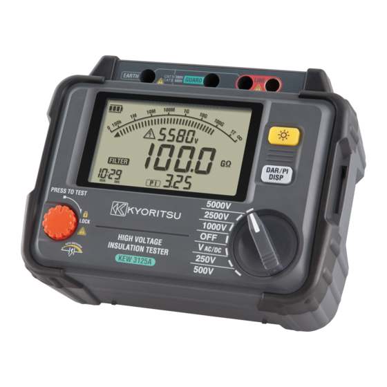
4. Instrument layout 4-1 Instrument layout 8 7 6 4 1 9 3 2 5 1 LCD display 2 Range Switch 3 Test button 4 Back Light button 5 DISP button 6 Line Terminal 7 Earth Terminal 8 Guard Terminal 9 Line Probe (red) 10 Earth Cord (black) 11 Guard Cord (green) 12 Protective figerguard I t is a part providing protection against electrical shock and ensuring the minimum required air and creepage distances. ̶ 10 ̶ 1.800.561.8187 information@itm.com www. .com... -
Page 13: Lcd Display
4-2 LCD display 5 2 4 3 1 6 9 7 8 1 Insulation resistance 2 Bar graph 3 Voltage monitor 4 Battery mark 5 Voltage warning mark 6 Timer display 7 DAR mark 8 PI mark 9 DAR/PI value 10 DC 11 AC 12 Minus display 13 Unit ̶ 11 ̶ 1.800.561.8187 information@itm.com www. .com... -
Page 14: How To Remove The Hard Case ・・・・・・・・・・・・・・・・・・・・・・12
4-3 How to remove the Hard case H old the side surface of the terminal part, and gently pull the unit toward the front. ① Hold the side surface of the terminal part. ② Pull the unit toward the front. ̶ 12 ̶ 1.800.561.8187 information@itm.com www. .com... -
Page 15: Getting Started ・・・・・・・・・・・・・・・・・・・・・・・・・・・・・・・・・・・・・・・・13
5. Getting started 5-1 Checking the battery voltage (1) Set the Range switch to any position other than OFF . (2) W hen the Battery mark shown at the upper left on the LCD is last one level , the batteries are almost exhausted. R eplace the batteries with new ones to perform further measurements. T he instrument operates properly even if under such a low battery level, and it may not affect on the accuracy. W hen the empty Battery mark appears, the battery voltage is below the lower limit of the operating voltage. So ... -
Page 16: Measurement ・ ・・・・・・・・・・・・・・・・・・・・・・・・・・・・・・・・・・・・・・・・・14
6. Measurement 6-1 Mains disconnection check (Voltage measurement) # DANGER ● N ever make measurements under the circumstances exceeding the designed measurement category and the rated voltage of the instrument and the test leads. ● W hen testing installations which have large current capacities, such as a power line, be sure to make measurement ... -
Page 17: Insulation Resistance Measurement ・・・・・・・・・・・・・・・・・・15
6-2 Insulation resistance measurement # DANGER ● U se a measuring apparatus, such as high voltage detector, and confirm that there is no electrical charge in the circuit under test. ● Wear a pair of insulated gloves for high voltage. ● I f the Range switch is at the insulation resistance range and the Test button is being pressed down, high voltages are generated and applied to the test leads and the circuit under test continuously. Do not touch the circuit or the test leads. ● T he Battery cover must be closed and screwed before starting a measurement. ● Never make measurement when thunder rumbling. ● C onnect the Earth Cord (black) to the earth terminal of the circuit under test. - Page 18 ●It takes time to measure a capacitive load. ● A t insulation resistance measurement, positive (+) voltage is outputted from the Earth terminal and negative (-) voltage is outputted from the Line terminal. Connect the Earth cord to the Earth (ground) terminal. I t is recommended to connect the positive(+) pole to the earth side when measuring insulation resistance against the ground or when a part of the equipment under test is earthed. W ith this connection, smaller measured value can be obtained comparing with other way round. (1) C heck the voltage which can be applied to the circuit under test, and set the range switch to a desired insulation ...
- Page 19 (5) This instrument has an auto-discharge function. W ith the test leads connected to the circuit under test, release the Test button to discharge capacitances in the circuit after test. Confirm that the indication on the voltage monitor becomes 0V . # DANGER ● D o not touch the circuit under test immediately after testing. C apacitances stored in the circuit may cause electric shock. ● L eave the test leads connected to the circuit and never touch the circuit until a discharge is complete. ...
-
Page 20: Continuous Measurement ・・・・・・・・・・・・・・・・・・・・・・・・・・18
Principle of Insulation Resistance Measurement A resistance value can be obtained by applying a certain high voltage to the resistor (insulation resistance) and measuring the flowing current. Resistance value = Voltage / Current (RX = V / I) 6-3 Continuous Measurement P ress and turn the Test button clockwise and lock the button to measure insulation resistances continuously. Turn the button counterclockwise and set it to the initial position after a measurement. # DANGER ● B e extremely careful not to get electric shock as a high voltage is present on the tip of the test leads continuously. ● ... - Page 21 Criteria Best Good Note1: DAR time is selectable: 15 or 30 sec. How to select: 1) K eep the DISP button pressed down and rotate the Range switch to power on KEW3125A/3025A. (DAR mark starts blinking.) 2) P ress the DISP button to switch 15 sec and 30 sec displayed at the lower left on the LCD. Select a desired one. 3) T hen power off the instrument. The selected DAR time will be saved and not be cleared even when the instrument is ...
- Page 22 3. How to measure DAR/ PI D AR and PI are automatically measured during a normal continuous measurement of insulation resistances. Set the Range switch to any desired range and measure the test object continuously. - 1 min after a start of continuous measurement: LCD shows DAR value. - 10 min after a start of continuous measurement: LCD shows PI value. When DAR/PI values are displayed as no : DAR ...
- Page 23 4. Display examples of DAR/ PI values T he DAR/PI values are displayed as follows during a measurement. (1) Start of test No DAR/PI value, “---” is displayed. (2) 1 min after the start of test DAR value is displayed. (3) 10 min after the start of test PI value is displayed.
- Page 24 (1) End of test (A) Time when a test ends Value measured at the end of test (resistance value) (C) DAR or PI value (2) Results at 15 or 30 sec after a start of test (A) Elapsed time (15 or 30 sec) Value measured 15 or 30 sec after a start of test. (resistance value, output voltage) (C) DAR value (3) Results at 1 min after a start of test (A) Elapsed time (1 min) Value measured 1 min after ...
-
Page 25: Voltage Characteristics At Measuring Terminal
6-5 Voltage characteristics at measuring terminal KEW3125A/3025A Output characteristics 6000 5000V range 5000 4000 3000 2500V range 2000 1000V range 1000 500V range 250V range 1000 1000 MΩ MΩ MΩ MΩ MΩ GΩ GΩ GΩ Insulation resistance 6-6 Use of Guard terminal ... -
Page 26: Backlight Function・ ・ ・・・・・・・・・・・・・・・・・・・・・・・・・・・・・・・・24
* I t is possible to move out the surface leakage resistance of the insulation and measure only the volume resistance by using the Guard terminal. This is helpful when performing tests in humid air. 6-7 Backlight function T his function to facilitate working at dimly illuminated location or at nighttime work. P ress the backlight button when the range switch is at any position ... -
Page 27: Battery Replacement
7.Battery replacement # DANGER ● D o not open the Battery compartment cover if the surface of the instrument is wet. ● N ever open the Battery compartment cover during a measurement. ● T o avoid possible electric shock, disconnect the test leads and Power Adaptor from the instrument before replacing batteries. After replacing batteries, make sure to tighten up the screw for the Battery compartment cover. # CAUTION ● Do not mix new and old batteries. ● M ake sure to install batteries in correct polarity as marked inside. (1) S et the Range switch to OFF ... -
Page 28: Accessories
8.Accessories 8-1 Metal parts for Line Probe, and replacement # DANGER Attach MODEL8255 to the test leads to use the instrument in CAT II or higher environments. MODEL8254 and 8019 have exposed large metal parts, therefore, they may short circuit the equipment under test and also may damage the equipments ... -
Page 29: How To Use The Adaptor For Recorder
8-2 How to use the adaptor for recorder MODEL8302 is an adaptor for a recorder (option) for output current measurement. Connect it as shown in the below figure. Output is DC1mV when current of 1μA is flowing. To shield To recorder or Earth - ̶ 27 ̶ 1.800.561.8187 information@itm.com www. .com... -
Page 30: Line Probe With Alligator Clip(Optional Accessory)
8-3 Line probe with alligator clip(optional accessory) (1) MODEL7168A Line probe with alligator clip (2) MODEL7253 Long Line probe with alligator clip (15m) ̶ 28 ̶ 1.800.561.8187 information@itm.com www. .com... -
Page 31: Disposing The Product
9. Disposing the Product Waste Electrical and Electronic Equipment (WEEE), Directive 2002/96/EC This Product complies with the WEEE Directive (2002/96/ EC) marking requirement. The affixed product label (see below) indicates that you must not discard this electrical/electronic product in domestic household waste. Product Category With ...
Need help?
Do you have a question about the KEW3125A and is the answer not in the manual?
Questions and answers