Table of Contents
Advertisement
Quick Links
Advertisement
Table of Contents

Related Manuals for Kyoritsu Electrical Instruments Works KEW 3126


Summary of Contents for Kyoritsu Electrical Instruments Works KEW 3126
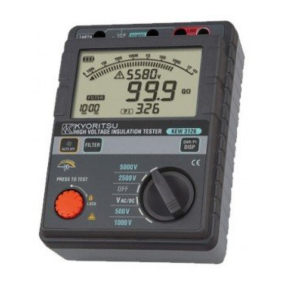
- Page 1 INSTRUCTION MANUAL 4-range High voltage insulation resistance tester KEW 3126...
-
Page 2: Table Of Contents
Contents 1. Safety warnings ·········································································· 1 2. Feature ······················································································· 5 3. Specification ··············································································· 6 4. Instrument layout 4-1 Instrument layout ·································································· 9 4-2 LCD display ········································································ 10 5. Preparation for measurement 5-1 Checking the battery voltage ·············································· 11 5-2 Connecting test leads ························································· 11 6. -
Page 3: Safety Warnings
1. Safety warnings This instrument has been designed, manufactured and tested according to IEC 61010: Safety requirements for Electronic measuring apparatus, and delivered in the best condition after passed the inspection. This instruction manual contains warnings and safety rules which must be observed by the user to ensure safe operation of the instrument and retain it in safe condition. - Page 4 # DANGER ● Never make measurement on the circuit in which electrical potential to ground over 600V exists. ● Do not attempt to make measurement in the presence of flammable gasses. Otherwise, the use of the instrument may cause sparking, which can lead to an explosion. ●...
- Page 5 # CAUTION ● Always make sure to set the Range switch to the appropriate position before making a measurement. ● Set the Range Switch to “OFF” position after use and disconnect the test leads from the instrument. Remove the batteries if the instrument is to be stored and will not be used for a long period.
- Page 6 ○ Measurement categories(Over-voltage categories) To ensure safe operation of measuring instruments, IEC 61010 establishes safety standards for various electrical environments, categorized as CAT I to CAT IV, and called measurement categories. Higher-numbered categories correspond to electrical environments with greater momentary energy, so a measuring instrument designed for CAT III environments can endure greater momentary energy than one designed for CATII.
-
Page 7: Feature
2. Feature KEW3126 is a microcomputer controlled, high voltage insulation resistance tester with 4-range for measuring insulation resistance. ● Designed to following safety standards: IEC 61010-1 (CAT.III 600V Pollution degree 2) IEC 61010-031 (Requirements for hand-held probes) ● With auto-discharge function When insulation resistance like a capacitive load is measured, electrical charges stored in capacitive circuits are automatically discharged after measuring. -
Page 8: Specification
3. Specification ● Applicable standards IEC 61010-1 Measurement CAT.III 600V Pollution degree2 IEC 61010-031 Standard for hand-held probes MODEL7165A(CAT.III 600V) MODEL7224A(CAT.IV 600V) MODEL7225A(CAT.IV 600V) * When KEW3126 and the test lead are combined and used together, whichever is lower category either of them belong to is applied. - Page 9 This monitor is used to check whether electrical charge stored on the equipment under test is discharged or not. The measured voltage value displayed on the LCD is a reference value. Please be noted that the indicated value, when external AC voltage is applied to the instrument, is not the correct value.
- Page 10 ●Overload protection: Insulation resistance range: AC1200V/10sec. Voltage range: AC720V/10sec. ●Withstand voltage: AC5320V(50/60Hz)/5sec. (Between electrical circuit and enclosure) ●Insulation resistance: 1000MΩ or more/DC1000V (Between electrical circuit and enclosure) ●Dimension: 205(L)×152(W)×94(D)mm ●Weight: approx. 1.8kg (battery included) ●Power source: DC12V: Alkaline battery size C(LR14)x 8pcs ●Current consumption (representative values at 12V of supply voltage) Range 500V...
-
Page 11: Instrument Layout
4. Instrument layout 4-1 Instrument layout LCD display Range switch Test button Back Light button FILTER button DAR/ PI DISP button Line Terminal Earth Terminal Guard Terminal 10 Line Probe (red) 11 Earth Cord (black) 12 Guard Cord (green) ̶ 9 ̶... -
Page 12: Lcd Display
4-2 LCD display 1 Insulation resistance 2 Bar graph 3 Voltage 4 Battery mark 5 Voltage warning mark 6 Time 7 DAR mark 8 PI mark 9 DAR/PI value 10 Filter mark 11 DC 12 AC 13 Minus sign 14 Unit 15 Overheat warning mark ̶... -
Page 13: Preparation For Measurement
5. Preparation for measurement 5-1 Checking the battery voltage (1) Set the Range switch to any position other than “OFF”. (2) When the battery mark shown at the upper left on the LCD is last 1 level , the batteries are almost exhausted. Replace the batteries with new ones to continue further measurements. -
Page 14: Measurement
6. Measurement 6-1 Mains disconnection check (Voltage measurement) # DANGER ● Do not make measurement on a circuit in which the electric potential exceeds AC/DC600V (voltage to ground) in order to avoid getting electrical shock. In addition, do not use this instrument when the voltage to ground is 600V or higher even the line voltage is 600V or less. -
Page 15: Insulation Resistance Measurement
6-2 Insulation resistance measurement # DANGER ● Confirm that no electrical charge exists on the circuit under test before measuring by using a high voltage detector. ● Put on a pair of insulated gloves for high voltage. ● In case the Range switch is set to Insulation resistance range, high voltage is being applied to the tips of test leads and to the circuit under test continuously while the Test button is kept pressed down. - Page 16 Connect the Earth cord to the Earth (ground) terminal. It is recommended to connect the positive(+) pole to the earth side when measuring insulation resistance against the ground or when a part of the equipment under test is earthed. With this connection, smaller measured value can be obtained comparing with other way round.
- Page 17 Auto-discharge function This is a function to discharge capacitance stored in the circuit under test automatically after testing. Discharge condition can be checked on the voltage monitor. This function will be canceled when removing the test leads 2 sec. or more before discharge completes.
-
Page 18: Continuous Measurement
Principle of Insulation Resistance Measurement Resistance value can be obtained by applying a certain high voltage to the resistance (insulation resistance) and measuring the flowing current. Resistance value = Voltage / Current (RX = V / I) LINE(-) RESISTANCE VALUE: RX VOLTAGE: V CURRENT: I EARTH(+) -
Page 19: Dar/Pi Measurement Function
6-4 DAR/PI Measurement function 1. PI – Polarization index This is to check a temporal increase of leakage currents flowing on insulations and to confirm leakage currents aren’t increased as time passes. PI is usually determined by the insulation resistances measured 1 min and 10 min after a measurement is started. - Page 20 (3) Press the FILTER button and confirm the selection. Selected DAR time is saved and kept after the instrument is powered off. To check the time currently selected, follow the step (1) described as above. 3. How to measure DAR/ PI DAR and PI are measured automatically at normal continuous measurement of insulation resistances.
- Page 21 4. How DAR/ PI values are displayed LCD shows DAR/PI values as shown below during measurements. (1) Start of test No DAR/PI value, “---” is displayed. (2) 1 min after the start of test DAR value is displayed. (3) 10 min after the start of test PI value is displayed.
- Page 22 5. How to review the measured DAR/PI values Press the DISP button when measurements end. The measured results are then displayed in following sequence. If the measure- ment ends earlier than the intervals described in below (2), (3) or (4), blank displays aren’t shown and returns to (1). (1) End of test (A) Time when a test ends (B) Value measured at the end...
-
Page 23: Voltage Characteristics Of Measuring Terminal
6-5 Voltage characteristics of measuring terminal KEW3126 Output characteristics 5000V range 2500V range 1000V range 500V range * for 10sec after a start of test 6-6 Use of Guard terminal When measuring the insulation resistance of a cable, leakage current flowing on the surface of cable jacket and the current flowing inside the insulator are mixed and may cause error in insulation resistance value. -
Page 24: Filter Function
Conductor L Insulation Leakage current Power supply Protective wire G Indicator E Cable with sheath (Insulation resistance tester) 6-7 Filter function KEW3126 has Filter function. Filter Mode is effective to reduce the variations in readings due to external influences during high resistance measurements. -
Page 25: Battery Replacement
7 . Battery replacement # DANGER ● Never open the battery compartment cover while making measurement. # WARNING ● To avoid getting possible electric shock, remove test leads before opening the battery compartment cover. After replacing batteries, make sure to tighten up the screw for battery compartment cover. -
Page 26: Accessories
8 . Accessories 8-1 Metal parts for Line Probe, and replacement # DANGER In the electrical environment of CAT.II or higher, MODEL8252 should be attached and used with the test lead. With the large exposed metal parts of MODEL8254 and 8019, the equipment under test may be shorted. -
Page 27: How To Use The Adaptor For Recorder
8-2 How to use the adaptor for recorder MODEL8302 is the adaptor for recorder (option) for output current measurement. Connect it as shown in the below figure. Output is DC1mA when current of 1μA is flowing. To recorder To shield or Earth −... - Page 28 DISTRIBUTOR Kyoritsu reserves the rights to change specifications or designs described in this manual without notice and without obligations. 10-04 92-2028...
Need help?
Do you have a question about the KEW 3126 and is the answer not in the manual?
Questions and answers