Table of Contents
Advertisement
Quick Links
Advertisement
Table of Contents

Related Manuals for Kyoritsu Electrical Instruments Works 4118A


Summary of Contents for Kyoritsu Electrical Instruments Works 4118A
- Page 1 INSTRUCTION MANUAL DIGITAL PSC-LOOP TESTER MODEL 4118A...
-
Page 2: Table Of Contents
CONTENTS 1. SAFE TESTING .................. 1 2. PROCEDURE OF REMOVING COVER ........... 4 3. FEATURES ..................5 3.1 Instrument Layout ................ 5 3.2 Test Lead ..................6 3.3 Features ..................7 4. SPECIFICATIONS ................9 5. OPERATING INSTRUCTIONS ............10 5.1 Initial Checks ................ -
Page 3: Safe Testing
1. SAFE TESTING This instrument has been designed and tested according to IEC Publication 61010: Safety Requirements for Electronic Measuring Apparatus. This instruction manual contains warnings and safety rules which must be observed by the user to ensure safe operation of the instrument and retain it in safe condition. - Page 4 DANGER ● The instrument is to be used only in its intended applications or conditions. Otherwise, safety functions equipped with the instrument will not work, and instrument damage or serious personal injury may occur. Verify proper operation on a known source before use or taking action as a result of the indication of the instrument.
- Page 5 CAUTION ● Do not expose the instrument to the direct sun, extreme temperatures or dew fall. ● Always make sure to insert each plug of the test leads fully into the appropriate terminal on the instrument. ● This instrument isn't dust & water proofed. Keep away from dust and water.
-
Page 6: Procedure Of Removing Cover
2. PROCEDURE OF REMOVING COVER Model 4118A have a dedicated cover to protect against an impact from the outside and prevent the operation part, the LCD and the connector socket from becoming dirty. The cover can be detached and put on the back side of the main body during measurement. -
Page 7: Features
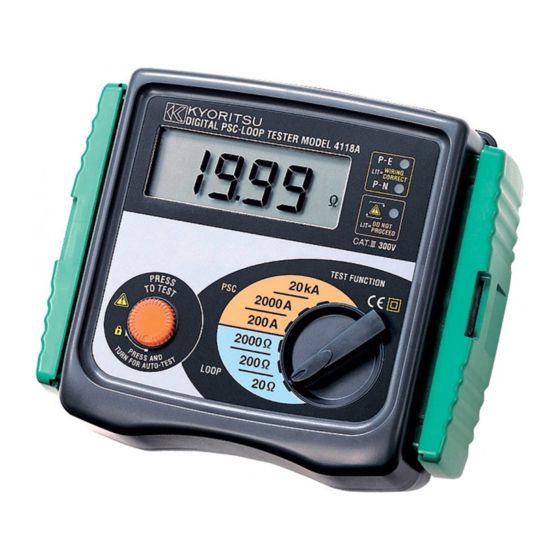
3. FEATURES 3.1 Instrument Layout ⑤ ① ② Wiring correct (Green LED's) Reversed L/N terminals (Red LED) ③ ④ Connector Fig. 3 1.... LCD display 2.... Wiring check LEDs 3.... Test button 4.... Range switch 5.... Connector DANGER ● Use original test lead only. ●... -
Page 8: Test Lead
3.2 Test Lead The instrument is supplied with Model 7125 lead at socket outlets and Model 7121B distribution board lead. (1) Model 7125 Mains lead mentioned in this instruction manual is Model 7125(EU) European SCHUKO plug, however, there are some other types for the areas, and the shipping is made along with the suitable plug-shaped cable according to the areas of the globe as follows;... -
Page 9: Features
As for the PSC range, use the following equation and divide supply voltage by loop impedance, therefore, the measured value shows smaller than the true value contrary to the case of the case of loop impedance range. ● PSC(A) = Supply Voltage(V) / Loop Impedance(Ω) Choose and use the test leads and caps that are suitable for the measurement category. - Page 10 3.3-3 Other Features: ● Battery is not used All models are not battery-operated, but operate by the voltage supplied from the system. ● Wiring check Three LEDs indicate if the wiring of the circuit under test is correct. The P-E and P-N LEDs illuminate when the wiring polarity of the circuit under test is correct.
-
Page 11: Specifications
4. SPECIFICATIONS ● Measurement Specification Loop Impedance Nominal test current Range Measuring range Accuracy at 0 Ω external loop 20 Ω 0.00 〜 19.99 Ω 25A / 20ms 200 Ω 0.0 〜 199.9 Ω 2.3A / 40ms ± (2%rdg + 4dgt) 2000 Ω... -
Page 12: Operating Instructions
● Operating Instrumental Uncertainty of Loop Impedance (61557-3) Measuring range to keep Maximum percentage operating Range operating error instrumental uncertainty 20 Ω 0.35 〜 19.99 Ω 200 Ω ± 30% 20.0 〜 199.9 Ω 2000 Ω 200 〜 1999 Ω The influencing variations used for calculating the operating instrumental uncertainty are denoted as follows: Temperature:0℃... -
Page 13: Measurement Of The Loop Impedance
WARNING ● If the above sequence is NOT displayed or the RED LED is on for any reason , DO NOT PROCEED AS THERE IS INCORRECT WIRING. The cause of the fault must be investigated and rectified. ● THE WIRING CHECK LED (P-E, P-N) of this instrument is to protect the user from electrical shock resulting from incorrect connection of Line and Neutral or Line and Earth. -
Page 14: Measurement Of Prospective Short Circuit Current
(6) Press the "Press to Test" button. The value of loop impedance will be displayed with the appropriate units. A bleep will sound on completion of the test. For best results always test on the lowest possible range. For example, a loop impedance measured on the 200Ω range may give an indication of 0.3Ω... -
Page 15: Detailed Explanation
(4) Check that the LED's are lit in the sequence indicated in section 5.1. If not, disconnect from the mains and check the wiring at the socket. (5) Press the "Press to Test" button. The prospective short circuit current (PSC) will be directly displayed on the LCD with the appropriate units. This will remain for 3s and then revert to AC voltage display. - Page 16 In the event of a fault, the Fault loop impedance should be low enough (and the Prospective Fault current higher enough) in order to have the automatic disconnection of supply by the installed protection device within prescribed time interval. ...
- Page 17 Ω RA (at 25V) Note: ● The loop tester models 4118A measure the fault loop impedance that is a value normally a little bit higher of RA. But, if the electrical installation is protected considering the loop impedance value, also the RA formula will be fulfilled.
- Page 18 Practical example of verification of the protection in a TT system according to the international Standard IEC 60364. Fig.8 For this example max value is 1667Ω, the loop tester reads 12.74Ω, it < means that the condition RA 50/Ia is respected. It is fundamental for this example to test also the RCD to ensure that operation takes place quickly enough to respect the safety requirements.
- Page 19 0.27 0.39 1020 0.22 Using the current ranges on models 4118A can be also tested the Prospective Fault current. Prospective Fault current measured by instruments must be higher than Ia of the protective device concerned Practical example of verification of the protection in a TN system according to the international Standard IEC 60364.
-
Page 20: Measurement Of Old-Tt System
Max value of Zs for this example is 2.1Ω (16A gG fuse, 0.4s) the loop tester reads 1.14 Ω (or 202 A on Fault current range) it means that the condition Zs < Uo/Ia is respected. In fact the Zs of 1.14Ω is less than 2.1Ω (or the Fault current of 202 A is more than Ia of 110A). -
Page 21: Measurement Of Line Impedance And Prospective Short Circuit Current
WARNING (OLD-TT system only) ● DO NOT PRESS the "Test button" if the display reads a value of 220V! 6.3 Measurement of Line Impedance and Prospective Short Circuit Current Line Impedance on single-phase system is the impedance measured between phase and neutral terminals. -
Page 22: Servicing
WARNING ● This instrument is intended only for use in single phase operation at 230V +10% -15% AC phase to earth or for use in OLD-TT system phase to neutral. ● If the overheat symbol appears in the display ( ) disconnect the instrument from the mains supply and allow to cool down. - Page 24 DISTRIBUTOR 92-2233A 4-19 Kyoritsu reserves the rights to change specifications or designs described in this manual without notice and without obligations.
Need help?
Do you have a question about the 4118A and is the answer not in the manual?
Questions and answers