
Related Manuals for Kyoritsu Electrical Instruments Works KEW SNAP Series


Summary of Contents for Kyoritsu Electrical Instruments Works KEW SNAP Series
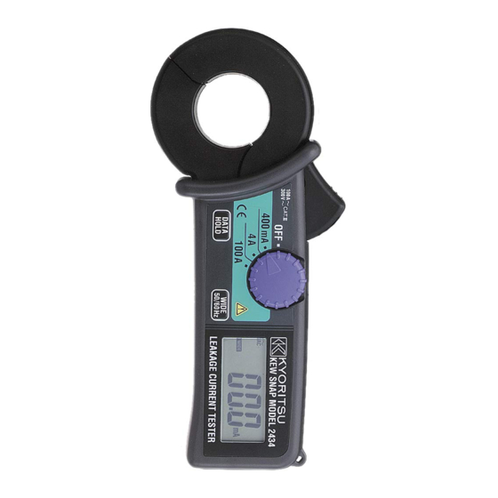
- Page 1 INSTRUCTION MANUAL LEAKAGE CURRENT TESTER KEW SNAP Series MODEL 2434 KYORITSU ELECTRICAL INSTRUMENTS WORKS, LTD., TOKYO, JAPAN...
-
Page 2: Safety Warnings
1. SAFETY WARNINGS This instrument has been designed and tested according to IEC Publication 61010: Safety Requirements for Electronic Measuring Apparatus. This instruction manual contains warnings and safety rules which must be observed by the user to ensure safe operation of the instrument and to retain it in safe condition. Therefore, read through ... -
Page 3: Specifications
WARNING ●Never attempt to make any measurement, if any abnormal conditions are noted, such as broken case, cracked test leads and exposed metal parts. ●Do not install substitute parts or make any modification to the instrument. Return the instrument to Kyoritsu or your distributor for repair or re-calibration. CAUTION ●Make sure that the range selector switch is set to an appropriate position before making measurement. ●Do not expose the instrument to the direct sun, extreme temperatures or dew fall. ... -
Page 4: Instrument Layout
Measuring method: Dual Integration Display: Liquid crystal display with maximum reading of 3999 Low battery warning: "BATT" mark appears on the display Overrange Indication: "OL" appears on the display when upper limit of measuring range is exceeded Response Time: Approx. 2 seconds Sample Rate: Approx. 2.5 times per second Accuracy-insured 23℃±5℃, relative humidity 85% or less Temperature and (without condensation) Humidity Ranges: Operating Temperature 0-40℃, relative humidity 85% or less and Humidity Ranges: (without condensation) Storage Temperature -20-60℃, relative humidity 85% or less and Humidity Ranges: (without condensation) Power Source: Two 1.5V R03 (UM-4) batteries Current Consumption: Approx. 4mA Measurement Time: Approx. 150 hours Sleep Function: Automatically powered down in about 10 minutes after the last switch operation Safety Standard: IEC 61010-1, IEC 61010-2-032... -
Page 5: Preparations For Measurement
5. PREPARATIONS FOR MEASUREMENT 5-1 Checking Battery Voltage Set the Range Selector Switch to any position other than the OFF position. If the marks on the display is clearly visible without "BATT" mark showing, battery voltage is OK. If the display blanks or "BATT" is indicated, replace the batteries according to section 8: Battery Replacement. NOTE When the instrument is left powered on, the Sleep function automatically shut the power off; The display blanks even if the Range ... -
Page 6: Leakage Current Measurement
6-1 Leakage Current Measurement (1)Set the Range Selector Switch to the desired position. Current to measure should be within the selected measuring range. (2)Measuring out of balance leakage current (See Fig.1): Clamp onto all conductors except a grounded wire. Measured current value is shown on the display. (3)Measuring earth leakage current (See Fig.2): Clamp onto a grounded wire.Measured current value is shown on the display. 3-phase 3-wire system Single-phase 2-wire system (In 4-wire system with neutral, (in 3-wire system with neutral, clamp onto all 4 wires) clamp onto all 3 wires) Fig. 1 Measuring out of balance leakage current ... - Page 7 Output characteristic are shown in Fig.3. 10 Typical characteristic: Typical characteristic: 400mA/4A Range WIDE frequency response ;;;; 100% 0 ;;;; Typical characteristic: 50% ;;;; 50/60Hz frequency response Typical characteristic: ー10 high-cut filter -24dB/oct 100A Range ;;;; 20% ;;;; ;;;; ー20 10% ;;;; 5% ー30 100 200 1k 2k 5k Frequency〔Hz〕 Fig.3 Model 2434 Frequency Characteristic Note: Characteristic of -24dB/octiave means that signal magnitude declines to about one sixteenth of that at the initial frequency when frequency doubles. Model 2434 have the following two settings for the Frequency Selector Button. ...
-
Page 8: Other Functions
7. OTHER FUNCTIONS 7-1 Sleep Function This is a function to prevent the instrument from being left powered on in order to conserve battery life. The instrument automatically enters the Sleep (powered-down) Mode about 10 minutes after the last switch operation. To exit the Sleep Mode, press the Data Hold or Frequency Selector Button or turn the Range Selector Switch to OFF, then to any other position. How to Exit the Sleep Mode: Turn the Range Selector Switch from to another position with the Data Hold Button pressed. Then, P.OFF is shown on the display. This disables the Sleep function and enables continuous use of the instrument. -
Page 9: Optional Accessories
9. OPTIONAL ACCESSORIES Model 8004 and 8008 (Multi-Tran) These models help Model 2434 to measure current greater than 1000A or to make measurement on a large bus-bar or conductor. (1)Set the Range Selector Switch to "100A". (2)As shown, open the jaws and close them over the pickup coil of Model 8004 or Model 8008. (3)Clamp on a conductor with Model 8004 or Model 8008. (4)Take the reading and multiply it by 10. Transformer jaws M -8 0 0 4 Conductor M -8 0 0 8 ... - Page 10 DISTRIBUTOR Kyoritsu reserves the rights to change specifications or designs described in this manual without notice and without obligations. KYORITSU ELECTRICAL INSTRUMENTS WORKS, LTD. No.5-20, Nakane 2― chome, Meguro-ku, Tokyo, 152-0031 Japan Phone: (03) 3723― 0131 Fax: (03) 3723― 0152 URL:http://www.kew-ltd.co.jp E-mail:info@kew-ltd.co.jp Factories:Uwajima&Ehime 02―05 92―1509...
Need help?
Do you have a question about the KEW SNAP Series and is the answer not in the manual?
Questions and answers