
Related Manuals for Hitachi PC-ARFG2-M


Summary of Contents for Hitachi PC-ARFG2-M
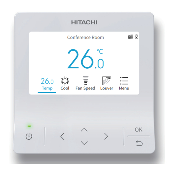
- Page 1 – INSTALLATION & MAINTENANCE MANUAL – Advanced Color Wired Remote Controller Conference Room MODELS Temp Cool Fan Speed Louver Menu PC-ARFG2-A PC-ARFG2-M PC-ARFG2-U ORIGINAL INSTRUCTIONS A16381TMEL...
- Page 2 Important Notice • Johnson Controls-Hitachi Air Conditioning pursues a policy of continuing improvement in design and performance in its products. As such, Johnson Controls-Hitachi Air Conditioning reserves the right to make changes at any time without prior notice. • Johnson Controls-Hitachi Air Conditioning cannot anticipate every possible circumstance that might involve a potential hazard.
-
Page 3: Table Of Contents
Table of Contents Table of Contents 1. Safety Summary ................................1 2. Installation Work ................................4 3. Electrical Wiring ................................6 4. Entering Service & Installation ............................7 5. Test Run ..................................8 6. Function Selection ...............................9 7. Input/Output Setting ..............................21 8. Main Remote Setting ..............................22 9. -
Page 4: Safety Summary
Use only Johnson Controls-Hitachi Air Conditioning recommended, provided as standardized, or replacement parts. • Johnson Controls-Hitachi Air Conditioning will not assume any liability for injuries or damage caused by not following steps outlined or described in this manual. Unauthorized modifications to Johnson Controls-Hitachi Air Conditioning products are prohibited as they…... - Page 5 1. Safety Summary Take the following precautions to reduce the risk of property damage. • Do not touch the main circuit board or electronic components in the controller or remote devices. Make sure that dust and/or steam does not accumulate on the circuit board. •...
- Page 6 When shielded cabling is applied, proper bonding and termination of the cable shield is required as per Johnson Controls-Hitachi Air Conditioning guidelines. Plenum and riser ratings for communication cables must be considered per application and local code requirements.
-
Page 7: Installation Work
2. Installation Work 2. Installation Work [Before Installation] (1) This packing contains the following parts. Installation & Maintenance PC-ARFG2-* Name Operation Manual Screw Manual Appearance M4 × 16mm Qty. ▲ ▲ ▲The manual quantity maybe one in some regions. (2) When arranging the advanced color wired remote controller and other controllers vertically, place them at least 2 inches(50mm) apart. - Page 8 2. Installation Work (2) Attach the controller to the holding bracket and connect the cable as follows. 1. In Case of Exposing the Controller Cable Draw-out Hole Cable D. Attach the stopper (plastic band) Band Stopper to the cable at the inside of (Field-Supplied) the draw-out hole.
-
Page 9: Electrical Wiring
When shielded cabling is applied, proper bonding and termination of the cable shield is required as per Johnson Controls-Hitachi Air Conditioning guidelines. Plenum and riser ratings for communication cables must be considered per application and local code requirements. -
Page 10: Entering Service & Installation
4. Entering Service & Installation 4. Entering Service & Installation Step1. Power On 1. Turn ON the power supply for all the indoor units. 2. For models equipped with an auto-address function, wait approximately 3 minutes. This function is being automatically performed. (There is a built-in 5-minute requirement according to the setting condition.) Step2. -
Page 11: Test Run
5. Test Run 5. Test Run Step1. Enter Installation Menu Service & Installation (Mon) 16:30 1. Select "Installation Menu" and press " OK". Service Menu Installation Menu Check Menu Select Back Step2. Enter "Test Run" Mode Installation Menu (Mon) 16:30 Test Run 1. -
Page 12: Function Selection
6. Function Selection 6. Function Selection Function Selection is set from Installation Menu. Step1. Select "Installation Menu" and press "OK" . Service & Installation (Mon) 16:30 Service Menu Installation Menu Check Menu Select Back Step2. Select "Function Selection "and press "OK". Installation Menu (Mon) 16:30 Test Run... - Page 13 6. Function Selection Table A. Optional Setting Items for Function Selection Individual Setting Item Optional Function Contents Setting Setting Condition Tset +4 C(default setting)(*2) Tset+0 C(no compensation) Set heating temperature ○ Tset+2 C (*3) compensation(*1) Tset+3 Tset+1 Circulator Function during Heating Unavailable ○...
- Page 14 6. Function Selection Individual Setting Item Optional Function Contents Setting Setting Condition Standard setting (7 steps) Change of Louver Swing Angle ○ Cold draft (5 steps) High ceilings (5 steps) Unavailable Power Supply ON/OFF 1 ○ Available Not used Not Used(Use as 00 setting conditions) Unavailable ○...
- Page 15 6. Function Selection Individual Setting Item Optional Function Contents Setting Setting Condition No Function • • • • Automatic OFF Timer Setting × 30 min. 90 min. 40 min. 45 min. Do not set them when two 50 min. wired controllers are used. 55 min.
- Page 16 6. Function Selection Individual Setting Item Optional Function Contents Setting Setting Condition C (Default setting) Lower limit for cooling temperature × setting (*9) C (Default setting) Upper limit for heating temperature × setting (*10) Not used Not used Not used Indication Indication of Hot Start ×...
- Page 17 6. Function Selection Individual Setting Item Optional Function Contents Setting Setting Condition -0.5 C(-1 -1.0 C(-2 -1.5 C(-3 -2.0 C(-3 -2.5 C(-4 -3.0 C(-5 Calibration for controller temp. -3.5 C(-6 × sensor +0.5 C(+1 +1.0 C(+2 +1.5 C(+3 +2.0 C(+3 +2.5 C(+4 +3.0...
- Page 18 6. Function Selection Individual Setting Item Optional Function Contents Setting Setting Condition Setting Position of Motion Sensor Not used Low air flow Select louver operation in energy- ○ Medium air flow saving Th.-OFF (COOL & DRY)(*12) High air flow Fan Speed during Energy-Saving Usual setting ○...
- Page 19 6. Function Selection Individual Setting Item Optional Function Contents Setting Setting Condition Not used Not used Not used Unavailable COOL only Operation mode with Setback × HEAT only COOL & HEAT 2.0°C(3°F) 3.0°C(5°F) Temp. differential for the Setback × 4.0°C(7°F) operation 5.0°C(9°F) 1.0°C (2°F)
- Page 20 6. Function Selection Individual Setting Item Optional Function Contents Setting Setting Condition 100h 200h 400h FrostWash interval settings × 100h 100h 100h 100h Unavailable 10 min. 20 min. 30 min. 40 min. 50 min. Minimum Cool/Heat Time for Auto × 60 min.
- Page 21 6. Function Selection Individual Setting Item Optional Function Contents Setting Setting Condition Unavailable 10.0°C (50°F) 11.0°C (52°F) 12.0°C (54°F) 13.0°C (56°F) 14.0°C (58°F) 15.0°C (59°F) 16.0°C (60°F) 17.0°C (62°F) 18.0°C (64°F) 19.0°C (66°F) 20.0°C (68°F) 21.0°C (70°F) 22.0°C (72°F) 23.0°C (74°F) 24.0°C (76°F) 25.0°C (77°F) 26.0°C (78°F)
- Page 22 6. Function Selection Individual Setting Item Optional Function Contents Setting Setting Condition 15.0°C (59°F) 16.0°C (60°F) 17.0°C (62°F) 18.0°C (64°F) Setback Activating Temp. for Heat 19.0°C (66°F) × Mode 10.0°C (50°F) 11.0°C (52°F) 12.0°C (54°F) 13.0°C (56°F) 14.0°C (58°F) 26.0°C (78°F) 27.0°C (80°F) 28.0°C (82°F) 29.0°C (84°F)
- Page 23 6. Function Selection NOTES: 1. Power ON, wait 3 minutes and then change the optional setting. 2. When changing the "CF" setting (changing the louver swing angle), restore the power supply or allow the louver to make one complete swing fully in the auto-swing mode to apply the optional setting.
-
Page 24: Input/Output Setting
7. Input/Output Setting 7. Input/Output Setting Set Input/output from the Installation Menu. Set Input/Output Service & Installation (Mon) 16:30 Step1. Select "Installation Menu" on the Service & Installation Service Menu screen and press "OK" . Installation Menu Check Menu Select Back Step2. -
Page 25: Main Remote Setting
8. Main Remote Setting Table B. Input and Output Number Display and Connectors Input Number Display Factory Setting Port Setting Input/Output Indication Setting Item Indication Input 1 CN3 1-2 Remote ON/OFF 1 (Level) Input 2 CN3 2-3 Forbidding Remote Control after Manual Stoppage Output 1 CN7 1-2 Operation... - Page 26 8. Main Remote Setting • Concerning main and sub controllers, the range of settings may differ for the functions shown below. Table D. Relation between Main/Sub Controller and Setting Range Function Main ○ × Power Saving Details Setting ○ × Details Setting Outdoor Unit Capacity Control...
-
Page 27: Priority Setting
9. Priority Setting 9. Priority Setting You can only set the operation mode and unit temperature setpoint from one specific controller (the main controller) in the same refrigerant system without having to use the central controller. The operation of sub controller is decided by the priority setting and power saving details setting of the main controller. -
Page 28: Frostwash
10. FrostWash 10. FrostWash FrostWash is available when applicable outdoor units and indoor units are connected. To use this function in VRF system, outdoor unit function selection item "F1" need to be configured on outdoor units. Please refer to the dedicated Service Manual for the FrostWash function. Please configure function selection F1 on the outdoor units, and then set the wired remote controller.* Please also refer to the Operation Manual and Service Manual of Wired Remote Controller for details. -
Page 29: Setback Trigger Unit
11. Setback Trigger Unit FrostWash setting on outdoor unit To use this function in the VRF system, function selection F1 needs to be configured on the outdoor units. FrostWash setting is disabled on the factory default setting.* Set Function Selection F1 according to the following table. Auto-FrostWash Manual FrostWash "F1"... -
Page 30: Operation Lock/Unlock Setting
12. Operation Lock/Unlock Setting 12. Operation Lock/Unlock Setting • This function disables the setting mode of the remote controller. Mode • In the operation lock, when the lock icon " " lights up, the mode cannot be changed by pressing " " or " ". •... -
Page 31: Password Setting
13. Password Setting 13. Password Setting The initial user password can be changed. If you forget the changed user password, a supervisor password can be used to set the user password again. The supervisor password is "5567". The password input effective time can be set also. It is not necessary to enter the password for a certain period after setting the password input effective time. -
Page 32: Hotel Mode Setting
14. Hotel Mode Setting 14. Hotel Mode Setting This setting enables or disables the hotel mode. Step1. Select "Service Menu" on the Service & Installation screen and press "OK". Step2. Select "Hotel Mode" and press "OK". Step3. Press " " or " " to select enabled setting. Step4. -
Page 33: Power Saving Details Setting
15. Power Saving Details Setting 15. Power Saving Details Setting This function provides the details for setting the power savings function. For the "Mode", select one item from each of the following settings, (1) outdoor unit capacity control, (2) indoor unit rotation control, and (3) intermittent control. - Page 34 15. Power Saving Details Setting Step7. Change level Intermittent Control Press " " or " " to select the item to set and press "OK". Low <-> Med <-> High It changes in the order of "Low <-> Med <-> High" ↔ "Low Low only only"...
- Page 35 15. Power Saving Details Setting Step6. Change the Fan Mode Time Rotation Control Select "Fan Mode Time" and press "OK". 10 min Press " " or " " to set the fan mode time. Press "OK" to 5 min confirm the setting. 3 min It changes as follows: "10 min"...
-
Page 36: Temperature Range Restriction
16. Temperature Range Restriction 16. Temperature Range Restriction The temperature range can be set by the wired remote controller. Set Temperature Range Step1. Select "Service Menu" on the Service & Installation screen Upper/Lower Limit for Cooling and press "OK". Step2. Select "Temperature Range Restriction" and press "OK". Step3. -
Page 37: Room Name Setting
19. Room Name Setting 19. Room Name Setting Register the installation location of the controller. Register Room Name Step1. Select "Service Menu" on the Service & Installation screen and press "OK". Step2. Select "Set Room Name" and press "OK". Step3. Press " " to move cursor to font type. Press " " or " " to Set Room Name select the font type. -
Page 38: Nfc Function
21. NFC Function 21. NFC Function Use the smart phone with NFC function to read and write all the setting data of the wired remote controller. When using NFC, you should make this setting enabled. The default setting is "Enable". NOTES: •... - Page 39 21. NFC Function (1) "NFC communication screen" for operations of reading & writing settings, canceling preheating control, operate test run, obtain error history and product information. Step1. Display the home screen on the wired remote controller and hold the "<" and ">" buttons simultaneously for 3 seconds.
-
Page 40: Backup System Setting
22. Backup System Setting 22. Backup System Setting This function is to setup the backup operation for multiple refrigerant system. The operation and standby of units can be set at selected rotation cycle time. NOTES: • This function is not available for one or more than five refrigerant systems. •... - Page 41 22. Backup System Setting 2. Backup operation when abnormality occurs If an abnormality occurs during the rotation operation, the standby refrigerant systems return back to operation. System Example System 1 System 2 Rotation procedure when abnormality occurs Abnormality occurs Operation Standby Operation Thermo-off...
-
Page 42: Backup System Setting Items
22. Backup System Setting 3. Backup operation in high load If there is a difference between the room temperature and the setting temperature (※1), the standby refrigerant systems start to operate. System Example System 1 System 2 Procedure of high load backup operation High load backup startup System1 Operation... -
Page 43: Set Backup System
22. Backup System Setting Choose 2 Systems Choose 1 System(default) Operation Operation System1 System1 Standby Standby Operation Operation System2 System2 Standby Standby Operation Operation System3 System3 Standby Standby Operation Operation System4 System4 Standby Standby Choose 3 Systems Operation System1 Standby Operation System2 Standby... - Page 44 22. Backup System Setting 3. Rotation Cycle Time Step1. Select "Rotation Cycle Time" on the backup system setting Rotation Cycle Time screen and press "OK". 9 hrs Step2. Press " " or " " to select the cycle time. 24 hrs Step3.
-
Page 45: Adjusting Date/Time
23. Adjusting Date/Time 23. Adjusting Date/Time Set the date and time. The setting is recommended in that it will be used to check the alarm history and set the schedule. Adjusting Date/Time Step1. While the air conditioner is stopped, press " " to select "Menu" and press "OK". While the air conditioner is operating, press "... - Page 46 © 2023 Johnson Controls-Hitachi Air Conditioning, Inc. 2023.05 Ver.A Printed in China...
Need help?
Do you have a question about the PC-ARFG2-M and is the answer not in the manual?
Questions and answers