Hitachi PC-ARFG2-Z Installation & Maintenance Manual
Advanced color wired remote controller
Hide thumbs
Also See for PC-ARFG2-Z:
- Operation manual (60 pages) ,
- Installation & maintenance manual (52 pages)

Subscribe to Our Youtube Channel
Related Manuals for Hitachi PC-ARFG2-Z


Summary of Contents for Hitachi PC-ARFG2-Z
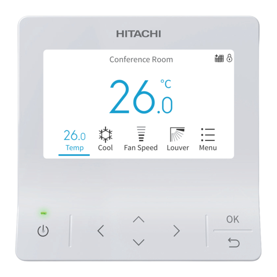
- Page 1 – INSTALLATION & MAINTENANCE MANUAL – Advanced Color Wired Remote Controller Conference Room MODEL Temp Cool Fan Speed Louver Menu PC-ARFG2-Z ORIGINAL INSTRUCTIONS A16381H9HF...
- Page 2 Important Notice • Johnson Controls-Hitachi Air Conditioning pursues a policy of continuing improvement in design and performance in its products. As such, Johnson Controls-Hitachi Air Conditioning reserves the right to make changes at any time without prior notice. • Johnson Controls-Hitachi Air Conditioning cannot anticipate every possible circumstance that might involve a potential hazard.
- Page 3 Table of Contents Table of Contents 1. Safety Summary ................................1 2. Installation Work ................................4 3. Electrical Wiring ................................6 4. Entering Service & Installation ............................7 5. Test Run ..................................8 6. Function Selection ...............................9 7. Input/Output Setting ..............................21 8. Main Remote Setting ..............................22 9.
- Page 4 Use only Johnson Controls-Hitachi Air Conditioning genuine replacement parts. • Johnson Controls-Hitachi Air Conditioning will not assume any liability for injuries or damage caused by not following steps outlined or described in this manual. Unauthorized modifications to Johnson Controls-Hitachi Air Conditioning products are prohibited as they: ○...
- Page 5 1. Safety Summary Take the following precautions to reduce the risk of property damage. • Do not touch the main circuit board or electronic components in the controller or remote devices. Make sure that dust and/or steam does not accumulate on the circuit board. •...
- Page 6 When shielded cabling is applied, proper bonding and termination of the cable shield is required as per Johnson Controls-Hitachi Air Conditioning guidelines. Plenum and riser ratings for communication cables must be considered per application and local code requirements.
- Page 7 This manual is applied for common use of the wired remote controller(connnected in non-zoning or zoning system). Refer to "Installation Work" of INSTALLATION & MAINTENANCE MANUAL of Premium Zoning Kit when connected in Zoning system. [Before Installation] (1) This packing contains the following parts. Installation & Maintenance PC-ARFG2-Z Name Operation Manual Screw Manual Appearance M4 ×...
- Page 8 2. Installation Work (2) According to different controller installation methods, choose one of the following two ways to install the mounting plate and connect the cable . Method 1 : To mount the controller directly on the surface of a wall: Draw-out Hole Cable D.
- Page 9 When shielded cabling is applied, proper bonding and termination of the cable shield is required as per Johnson Controls-Hitachi Air Conditioning guidelines. Plenum and riser ratings for communication cables must be considered per application and local code requirements.
- Page 10 4. Entering Service & Installation 4. Entering Service & Installation Some functions are not available when the wired remote controller is connected in Zoning system, please see 26.3 Features Not Available When Connected with Zoning Kit for details. Step1. Power On 1.
- Page 11 5. Test Run 5. Test Run Test Run is to run the indoor units whether any pipe or cables is Service & Installation (Mon) 16:30 incorrectly installed. Service Menu Step1. Enter Installation Menu Installation Menu 1. Select "Installation Menu" and press "...
- Page 12 6. Function Selection 6. Function Selection Function Selection is set from Installation Menu. Step1. Select "Installation Menu" and press "OK" . Service & Installation (Mon) 16:30 Service Menu Installation Menu Check Menu Select Back Step2. Select "Function Selection "and press "OK". Installation Menu (Mon) 16:30 Test Run...
- Page 13 6. Function Selection Table A. Optional Setting Items for Function Selection Individual Setting Item Optional Function Contents Setting Setting Condition Tset +4 C(default setting)(*2) Tset+0 C(no compensation) Set heating temperature ○ Tset+2 C (*3) compensation(*1) Tset+3 Tset+1 Circulator Function during Heating Unavailable ○...
- Page 14 6. Function Selection Individual Setting Item Optional Function Contents Setting Setting Condition Standard setting (7 steps) ○ Change of Louver Swing Angle Cold draft (5 steps) High ceilings (5 steps) Unavailable ○ Power Supply ON/OFF 1 Available Not used Not Used(Use as 00 setting conditions) Unavailable Power Supply ON/OFF 2 ○...
- Page 15 6. Function Selection Individual Setting Item Optional Function Contents Setting Setting Condition No Function • • • • Automatic OFF Timer Setting × 30 min. 90 min. 40 min. Do not set them when two 45 min. wired remote controllers 50 min.
- Page 16 6. Function Selection Individual Setting Item Optional Function Contents Setting Setting Condition C (Default setting) Lower limit for cooling temperature × setting (*9) C (Default setting) Upper limit for heating temperature × setting (*10) Not used Not used Not used Indication Indication of Hot Start ×...
- Page 17 6. Function Selection Individual Setting Item Optional Function Contents Setting Setting Condition -0.5 C(-1 -1.0 C(-2 -1.5 C(-3 -2.0 C(-3 -2.5 C(-4 -3.0 C(-5 Calibration for controller temp. -3.5 C(-6 × sensor +0.5 C(+1 +1.0 C(+2 +1.5 C(+3 +2.0 C(+3 +2.5 C(+4 +3.0...
- Page 18 6. Function Selection Individual Setting Item Optional Function Contents Setting Setting Condition Setting Position of Motion Sensor Not used Low air flow Select louver operation in energy- ○ Medium air flow saving Th.-OFF (COOL & DRY)(*12) High air flow Fan Speed during Energy-Saving Usual setting ○...
- Page 19 6. Function Selection Individual Setting Item Optional Function Contents Setting Setting Condition Not used Not used Not used Unavailable COOL only Operation mode with Setback × HEAT only COOL & HEAT 2.0°C(3°F) 3.0°C(5°F) Temp. differential for the Setback × 4.0°C(7°F) operation 5.0°C(9°F) 1.0°C (2°F)
- Page 20 6. Function Selection Individual Setting Item Optional Function Contents Setting Setting Condition 100h 200h 400h FrostWash interval settings × 100h 100h 100h 100h Unavailable 10 min. 20 min. 30 min. 40 min. 50 min. Minimum Cool/Heat Time for Auto × 60 min.
- Page 21 6. Function Selection Individual Setting Item Optional Function Contents Setting Setting Condition Unavailable 10.0°C (50°F) 11.0°C (52°F) 12.0°C (54°F) 13.0°C (56°F) 14.0°C (58°F) 15.0°C (59°F) 16.0°C (60°F) 17.0°C (62°F) 18.0°C (64°F) 19.0°C (66°F) 20.0°C (68°F) 21.0°C (70°F) 22.0°C (72°F) 23.0°C (74°F) 24.0°C (76°F) 25.0°C (77°F) 26.0°C (78°F)
- Page 22 6. Function Selection Individual Setting Item Optional Function Contents Setting Setting Condition 15.0°C (59°F) 16.0°C (60°F) 17.0°C (62°F) 18.0°C (64°F) Setback Activating Temp. for Heat 19.0°C (66°F) × Mode 10.0°C (50°F) 11.0°C (52°F) 12.0°C (54°F) 13.0°C (56°F) 14.0°C (58°F) 26.0°C (78°F) 27.0°C (80°F) 28.0°C (82°F) 29.0°C (84°F)
- Page 23 6. Function Selection NOTES: 1. Power ON, wait 3 minutes and then change the optional setting. 2. When changing the "CF" setting (changing the louver swing angle), restore the power supply or allow the louver to make one complete swing fully in the auto-swing mode to apply the optional setting.
- Page 24 7. Input/Output Setting 7. Input/Output Setting Set Input/output from the Installation Menu. Please refer to Table B and Table C for details on each input setting. Set Input/Output Service & Installation (Mon) 16:30 Step1. Select "Installation Menu" on the Service & Installation Service Menu screen and press "OK"...
- Page 25 8. Main Remote Setting Table B. Input and Output Number Display and Connectors Input Number Display Factory Setting Port Setting Input/Output Indication Setting Item Indication Input 1 CN3 1-2 Remote ON/OFF 1 (Level) Input 2 CN3 2-3 Forbidding Remote Control after Manual Stoppage Output 1 CN7 1-2 Operation...
- Page 26 8. Main Remote Setting • Concerning main and sub controllers, the range of settings may differ for the functions shown below. Table D. Relation between Main/Sub Controller and Setting Range Function Main ○ × Power Saving Details Setting ○ × Details Setting Outdoor Unit Capacity Control...
- Page 27 9. Priority Setting 9. Priority Setting You can only set the operation mode and unit temperature setpoint from one specific controller (the main controller) in the same refrigerant system without having to use the central controller. The operation of sub controller is decided by the priority setting and power saving details setting of the main controller.
- Page 28 10. FrostWash 10. FrostWash FrostWash is available when applicable outdoor units and indoor units are connected. To use this function in VRF system, outdoor unit function selection item "F1" need to be configured on outdoor units. Please refer to the dedicated Service Manual for the FrostWash function. Please configure function selection F1 on the outdoor units, and then set the wired remote controller.* Please also refer to the Operation Manual and Service Manual of Wired Remote Controller for details.
- Page 29 11. Setback Trigger Unit FrostWash setting on outdoor unit To use this function in the VRF system, function selection F1 needs to be configured on the outdoor units. FrostWash setting is disabled on the factory default setting.* Set Function Selection F1 according to the following table. Auto-FrostWash Manual FrostWash "F1"...
- Page 30 12. Operation Lock/Unlock Setting 12. Operation Lock/Unlock Setting • This function disables the setting mode of the remote controller. Mode • In the operation lock, when the lock icon " " lights up, the mode cannot be changed by pressing " " or " ". •...
- Page 31 13. Password Setting 13. Password Setting The default user password can be changed. If you forget the changed user password, a supervisor password can be used to reset the user password again. The supervisor password is "5567". The password input effective time can be set also. If the password input effective time has been set, then the password is required to be entered only once during the password effective time.
- Page 32 14. Hotel Mode Setting 14. Hotel Mode Setting This setting enables or disables the hotel mode. Step1. Select "Service Menu" on the Service & Installation screen and press "OK". Step2. Select "Hotel Mode" and press "OK". Step3. Press " " or " " to select enabled setting. Step4.
- Page 33 15. Power Saving Details Setting 15. Power Saving Details Setting This function provides the details for setting the power savings function. For the "Mode", select one item from each of the following settings, (1) outdoor unit capacity control, (2) indoor unit rotation control, and (3) intermittent control.
- Page 34 15. Power Saving Details Setting Step7. Change level Intermittent Control Press " " or " " to select the item to set and press "OK". Low <-> Med <-> High It changes in the order of "Low <-> Med <-> High" ↔ "Low Low only only"...
- Page 35 15. Power Saving Details Setting Step6. Change the Fan Mode Time Rotation Control Select "Fan Mode Time" and press "OK". 10 min Press " " or " " to set the fan mode time. Press "OK" to 5 min confirm the setting. 3 min It changes as follows: "10 min"...
- Page 36 16. Temperature Range Restriction 16. Temperature Range Restriction The temperature range can be set by the wired remote controller. Set Temperature Range Temperature Range Restriction Step1. Select "Service Menu" on the Service & Installation screen Upper/Lower Limit for Cooling and press "OK". Upper/Lower Limit for Heating Step2.
- Page 37 18. Main/Sub Display Setting 18. Main/Sub Display Setting The main or sub display of the remote controller can be turned off. Set the main/sub display invisible. Step1. Select "Service Menu" on the Service & Installation screen Conference Room and press "OK". Step2.
- Page 38 20. Contact Information Registration 20. Contact Information Registration Register a service contact (service address and service telephone number are recommended). Register Contact Information Step1. Select "Service Menu" on the Service & Installation screen and press "OK". Step2. Select "Set Contact Information" and press "OK". Step3.
- Page 39 21. NFC Function 21. NFC Function Use the smart phone with NFC function to read and write all the setting data of the wired remote controller. When using NFC, you should make this setting enabled. The default setting is "Enable". NOTES: •...
- Page 40 21. NFC Function (1) "NFC communication screen" for operations of reading & writing settings, canceling preheating control, operate test run, obtain error history and product information. Step1. Display the home screen on the wired remote controller and hold the "<" and ">" buttons simultaneously for 3 seconds.
- Page 41 22. Backup System Setting 22. Backup System Setting This function is to setup the backup operation for multiple refrigerant system. The operation and standby of units can be set at selected rotation cycle time. NOTES: • This function is not available for one or more than five refrigerant systems. •...
- Page 42 22. Backup System Setting 2. Backup operation when abnormality occurs If an abnormality occurs during the rotation operation, the standby refrigerant systems return back to operation. System Example System 1 System 2 Rotation procedure when abnormality occurs Abnormality occurs Operation Standby Operation Thermo-off...
- Page 43 22. Backup System Setting 3. Backup operation in high load If there is a difference between the room temperature and the setting temperature (※1), the standby refrigerant systems start to operate. System Example System 1 System 2 Procedure of high load backup operation High load backup startup System1 Operation...
- Page 44 22. Backup System Setting Choose 2 Systems Choose 1 System(default) Operation Operation System1 System1 Standby Standby Operation Operation System2 System2 Standby Standby Operation Operation System3 System3 Standby Standby Operation Operation System4 System4 Standby Standby Choose 3 Systems Operation System1 Standby Operation System2 Standby...
- Page 45 22. Backup System Setting 3. Rotation Cycle Time Step1. Select "Rotation Cycle Time" on the backup system setting Rotation Cycle Time screen and press "OK". 9 hrs Step2. Press " " or " " to select the cycle time. 24 hrs Step3.
- Page 46 23. Adjusting Date/Time 23. Adjusting Date/Time Set the date and time. The setting is recommended in that it will be used to check the alarm history and set the schedule. Adjusting Date/Time Step1. While the air conditioner is stopped, press " " to select "Menu" and press "OK". While the air conditioner is operating, press "...
- Page 47 25. ESP Setting 25. ESP Setting This function is used for adjusting External Static Pressure (ESP). It is available only for selected airCore 700 ducted indoor units that support this feature. NOTES: • This function is exclusively available when the system is connected to airCore 700 ducted indoor units that support Auto ESP setting.
- Page 48 25. ESP Setting Step3. Press " "or " " to select the setting and press "OK" ESP Standard Setting to confirm the setting. Standard Hi speed 1 Hi speed 2 Select Back Step4. Press " " to return to Step2 screen. Pressing " ", " ", "...
- Page 49 25. ESP Setting ESP Auto Setting b. Press "OK" in Checking ESP screen. Stop Auto ESP now? b-1 Select "Yes" and press "OK" to stop auto ESP, select "Continue" and return to Step2 to select Cancel another indoor unit for auto ESP. Or select "Complete" to return to Step1.
- Page 50 25. ESP Setting ESP Setting 5. Display ESP Setting ESP Standard Setting Step1. Select "Display ESP Setting" on the ESP Setting screen ESP Auto Setting and press "OK". ESP Manual Setting Display ESP Setting Select Back Display ESP Setting Step2. Select the indoor unit by pressing " ", " ", " ", or " " and press "OK".
- Page 51 26. Premium Zoning Function 26. Premium Zoning Function 26.1 Zone Installation Menu If the wired controller is connected to the zone interface box, "Zone Installation Menu" is displayed in "Service & Installation Menu". For the way of activating zoning kit function, please see Installation and Maintenance Manual of Zone Interface Box.
- Page 52 26. Premium Zoning Function 26.1.2 Zone Activation This function is to enable or disable zone from zone1 to zone8. Step1. Select "Zone Activation" and press "OK". Zone Installation Menu (Mon) 16:30 Common Zone Setup Zone Actisation Zone Labeling Nominate Spill Zone(s) Sensor Assignment OK Select Back...
- Page 53 26. Premium Zoning Function Step6. The confirmation screen is displayed. Zone Labeling Select "Yes" and press "OK" to confirm the settings Bedroom 2 and Step2 is displayed. Register these contents ? Select Bac9 26.1.4 Nominate Spill Zone(s) Step1. Select "Nominate Spill Zone(s)" and press "OK". Zone Installation Menu (Mon) 16:30 Common Zone Setup...
- Page 54 26. Premium Zoning Function 26.1.5 Sensor Assignment This function is to assign the specified sensor to the activated zone. Step1. Select "Sensor Assignment" and press "OK". Zone Installation Menu (Mon) 16:30 Common Zone Setup Zone Actisation Zone Labeling Nominate Spill Zone(s) Sensor Assignment OK Select Back...
- Page 55 26. Premium Zoning Function Step3. Press " " or " " to select the item. Airflow unit: L/s Press " " or " " to set value(unit: L/s). Back Step4. Select " " and press "OK" to save the setting and return to Step2.
- Page 56 26. Premium Zoning Function 26.1.9 Turn on All Zones This function is to turn on all the activated zones at the same time. Step1. Select "Turn on All Zones" and press "OK". Zone Installation Menu Airflow Minimum Airflow Ratio Damper Timing Turn On All Zones OK Select Back...
- Page 57 © 2023 Johnson Controls-Hitachi Air Conditioning, Inc. 2023.09 Ver.A Printed in China...
Need help?
Do you have a question about the PC-ARFG2-Z and is the answer not in the manual?
Questions and answers