
Related Manuals for Toyota 55405-05160


Summary of Contents for Toyota 55405-05160
- Page 1 Avensis TNS700 RHD installation instructions Model year: 2006 Vehicle code: **T25*R-*****W Part number: • Navigation System 08545-00950 • Audio Frame 55405-05160 Manual ref. n : AIM 001 067-0...
- Page 2 TNS 700 Avensis (T25) PRECAUTIONS PLEASE READ THOROUGHLY THESE PRECAUTIONS BEFORE THE INSTALLATION • Protect your car with fender cov- • Be sure to disconnect the negative ers, seat and so on. (-) lead from the battery terminals. • Use the correct tool when tight- •...
-
Page 3: Table Of Contents
TNS 700 Avensis (T25) TABLE OF CONTENTS Precautions ............................. Component parts ........................... Navigation Kit ............................How to connect ............................. Installation Overview ..........................Vehicle Disassembly ..........................Installation of the GPS-Antenna ......................Wire Harness Installation ......................... Installation of the Navigation Disc ......................Post-Installation Inspection ........................ -
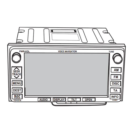
Page 4: Component Parts
PWR•VOL VOICE NAVIGATION TUNE SEEK TRACK MENU DEST INFO VOICE AUDIO DISPLAY TILT OPEN TOYOTA B-9001 Description TNS700 WIRE HARNESS GPS ANTENNA NAVIGATION DISC WIRE CLAMP FOAM TAPE 2 + 3 WIRE TIE EARTH PLATE 01-07 Avensis (RHD) - 4... - Page 5 TNS 700 Avensis (T25) Avensis (T25) TNS 600 COMPONENT PARTS 55405-05160 OWNER’S MANUAL To be ordered separately. Refer to ATA database for partnumbers Avensis (RHD) - 5 01-07...
-
Page 6: How To Connect
Avensis (T25) TNS 700 Avensis (T25) TNS00 HOW TO CONNECT TNS 700 Tuner with LCD Display Splicing connector Splicing connector (Speed sensor wire) (Reverse sensor wire) GPS antenna Vehicle wire harness Antenna wire Refer to the repair manual for information on removal of vehicle parts, installation methods, tightening torque etc. -
Page 7: Installation Overview
TNS 700 Avensis (T25) INSTALLATION OVERVIEW GPS antenna Antenna wire Splicing connector (Speed reverse Sensor with pre wire) Splicing connector (Speed Sensor without pre wire) Splicing connector (Reverse Sensor without pre wire) Avensis (RHD) - 7 01-07... -
Page 8: Vehicle Disassembly
TNS 700 Avensis (T25) VEHICLE DISASSEMBLY FOR M/T MODELS Remove the gear lever knob FOR ALL MODELS b) Remove the gear lever hole cover : Clip (4x) Fig. 1 Remove the instrument panel cluster moulding : Clip (5x) Fig. 2 Remove the heater control assembly : Bolt (4x) Fig. - Page 9 TNS 700 Avensis (T25) Remove the storage box : Screw (2x) : Clip (2x) Fig. 4 Avensis (RHD) - 9 01-07...
-
Page 10: Installation Of The Gps-Antenna
TNS 700 Avensis (T25) INSTALLATION OF THE GPS-ANTENNA Cut the foam (d) into 12 pieces as shown in the illustration. Fig. 5 Remove the release paper of the earth plate and attach the butyl tape shown. b) Apply the tapes to the adhesive side of the earth plate Fig. - Page 11 TNS 700 Avensis (T25) Route the GPS antenna wire shown. Fig. 8 Avensis (RHD) - 11 01-07...
-
Page 12: Wire Harness Installation
TNS 700 Avensis (T25) WIRE HARNESS INSTALLATION CONNECTING PROCEDURES OF Splicing connector SPLICING CONNECTOR Pliers Remove the vinyl tube or wrapping tape from the length of vehicle wire harness to be connected. b) Insert the vehicle wire harness to beconnected securely into the guide slit. - Page 13 TNS 700 Avensis (T25) Cut the red/white wire away isolate Fig. 12 FOR VEHICLES WITHOUT PRE-WIRE Route the reverse sensor wire shown in the illustration. 10P (white) 20P (white) Fig. 13 Connect speed sensor wire (Violet/White) to terminal 3 of the 20P (white) 20P Wire side vieuw 20P (White) connector.
- Page 14 TNS 700 Avensis (T25) Route the reverse sensor wire Recerse sensor wire shown in the illustration. b) Disconnect the 18P (White) connector. 18P (white) Fig. 15 Connect the reverse sensor wire (Green) to terminal 8 f the 18P (White) con- 18P Wire side vieuw 18P (white) nector.
- Page 15 TNS 700 Avensis (T25) Secure the excess speed sensor wire Recerse sensor wire and reverse sensor wire as shown in Speed sensor wire the illustration using the foam tape Foam tape x 2 Fig. 18 Remove the speed signal from 20 pin connector (pin 3) Fig.
- Page 16 TNS 700 Avensis (T25) Slight the airco to the left to disassem- le the airco. PWR•VOL SEEK TRACK DUAL TEMP Fig. 21 Slight (put) the frame on the airco and mount the brackets on the TNS700 and the airco. b) Connect the connectors and place the headunit back in place.
- Page 17 TNS 700 Avensis (T25) 12. Re fit all parts. AUTO DUAL TEMP TEMP Fig. 24 ENSURE THAT ALL REMOVED CONNECTORS ARE PUT BACK CORRECTLY. REFIT THE TRIM AND REMOVED PARTS. Avensis (RHD) - 17 01-07...
-
Page 18: Installation Of The Navigation Disc
Manual, and confirm that the sound from the speakers changes. 4. Perform the “auto-compensation” procedure by following the section on “When Tires are Replaced” in the TNS700 Owner’s Manual. When an abnormality is suspected, perform troubleshooting based on the “Toyota Genuine Navigation System Service Manual”. REASSEMBLING Return all vehicle parts that have been removed to their original locations. - Page 19 GENUINE PARTS...
Need help?
Do you have a question about the 55405-05160 and is the answer not in the manual?
Questions and answers