
Related Manuals for Jøtul F 370


Summary of Contents for Jøtul F 370
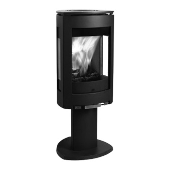
- Page 1 Jøtul F 370 US/CAN 10036803_P14 Jøtul F 370 Woodburning Stove Installation and Operating Instructions for the United States & Canada Keep these instructions for future reference.
-
Page 2: Table Of Contents
Attach your sales receipt to Installation this manual for future reference. 4.1 Chimney Requirements ..........5 4.2 Chimney Connector Requirements ......7 Model: Jøtul F 370 Serial Number: 4.3 Floor Protection ............. 10 4.4 Clearance to Combustible Materials ......10 Purchase Date: Assembly 5.1 Tools &... -
Page 3: Standards And Codes
Avis de sécurité: Une installation non When installing, operating and maintaining your appropriée de ce poêle de chauffage risque de Jøtul F 370 Fireplace Insert, follow the guidelines provoquer un incendie. Assurez votre sécurité presented in these instructions, and make them available en respectant les directives d’installation... -
Page 4: Specifications
9 3/4” 247mm 17 1/2” 17 3/4” 442mm 452mm 13 1/4” 13 3/4” 336mm 324mm 19 1/2” 495mm 40 1/2” 45 1/2” 1031mm 1156mm Rear Exit Centerline 18 5/8” 18 1/4” 465mm 473mm Figure 1. Jøtul F 370 critical dimensions. -
Page 5: Safety Requirements
Jøtul F 370 US/CAN 10036803_P14 3. Safety Notices 4. Installation Requirements • BURN SOLID WOOD FUEL ONLY 4.1 Chimney Requirements • DO NOT USE CHEMICALS OR FLUIDS TO START There are two types of approved chimneys: THE FIRE. DO NOT BURN GARBAGE, TRASH, OR 1. - Page 6 Jøtul F 370 US/CAN 10036803_P14 4.1.1 Masonry Chimneys 4.1.3 Chimney Height Follow these guidelines when installing the stove into a The chimney must be at least 3 feet (92 cm) higher than masonry fireplace: the highest point where it passes through the roof and at •...
-
Page 7: Chimney Connector Requirements
Jøtul F 370 US/CAN 10036803_P14 4.2 Chimney Connector Requirements Use 6” single wall or listed 6” double-wall stovepipe to connect the stove to the chimney. Single wall stovepipe must be black steel or stainless steel and have a minimum thickness of 24 gauge. - Page 8 Jøtul F 370 US/CAN 10036803_P14 The connector pipe or thimble sleeve must not protrude into the flue liner or otherwise restrict draft. Use refractory cement to seal the seam between the chimney connector, sleeve, and thimble. Do not connect this stove to a chimney flue servicing another appliance of any kind.
- Page 9 Jøtul F 370 US/CAN 10036803_P14 4.2.2 Wall Pass-Throughs Flue Liner Note: In addition to the methods described here, any Clearance 2” listed, prefabricated wall pass-through components available from chimney manufacturers may be used. Chimney Wall In the U.S. The National Fire Protection Association’s publication,...
-
Page 10: Floor Protection
U.S. connectors. Minimum Ceiling Height: 72” / 183 cm The F 370 is approved for use with Listed double wall pipe installed to conform to the clearances in fig. 8a. Wall-Mounted Protection: When reducing clearances through the use of wall-mounted protection: For the U.S. - Page 11 350mm 362mm 400mm Figure 8a. Clearance Diagrams. 4.4.3 Alcove Installations The Jøtul F 370 can be installed in an alcove as diagrammed in fig. 9. 1. The stove must be installed only with double-wall chim- 7” ney connector. 2. Wall protection must extend over the entire area.
-
Page 12: Assembly
Jøtul F 370 US/CAN 10036803_P14 5. Assembly If the Rotation Kit will be installed, use the assembly instructions provided with that kit. 5.1 Tools & Materials • work gloves • safety glasses • tape measure • 4 mm hex key •... -
Page 13: Assemble The Firebox And Pedestal
Jøtul F 370 US/CAN 10036803_P14 Acorn Nuts 5.4 Attach the Firebox to the Pedestal 1. Spread the shipping carton out to protect the floor 2 1/2” Lag and carefully lay the firebox on its side. Bolt 2. Use a 13 mm wrench to remove the four, M8 x 25 mm bolts from the bottom of the firebox as shown in fig. -
Page 14: Position The Stove
Jøtul F 370 US/CAN 10036803_P14 5.5 Position the Stove Air Outlet 1. Use the clearance diagrams and associated flue collar Grille connection center-line dimensions to determine the stove location appropriate to the clearance requirements specific to your installation. See fig, 8... -
Page 15: Secure Stove To Hearth
Jøtul F 370 US/CAN 10036803_P14 5.7 Secure the stove to the hearth 1. At the anchor bracket hole, drill a 1/4” dia. pilot hole through the hearth and into the floor material. NOTE: For masonry floor materials, install a 3/8” dia. -
Page 16: Operation
Jøtul F 370 US/CAN 10036803_P14 6. Operation 6.2 Air Control Settings A single lever regulates the Primary Air flow that controls the intensity of the fire and consequent heat output and Read the following section carefully before building a fire burn time. -
Page 17: Starting A Fire
Jøtul F 370 US/CAN 10036803_P14 6.3 Starting and Maintaining a Fire Burn only solid wood directly on the bottom plate of the stove. Do not elevate the fire in any way. Use the following guide for best performance. 1. Set the Air Control Lever in the full open position, all the way to the right. -
Page 18: Adding Fuel
Jøtul F 370 US/CAN 10036803_P14 6.5 Adding Fuel to the Fire A chimney flue located within the home interior When reloading the stove while a bed of hot embers still will benefit from the insulating characteristics of the exists, follow this reloading procedure: building itself. -
Page 19: Maintenance
CRACKED OR BROKEN GLASS PANEL. Replace glass only with panels specifically The Jøtul F370 is designed to burn cleanly and efficiently designed for the Jøtul F 370. Do not use when used according to the guidelines in this manual. substitutes. Replacement glass can be... -
Page 20: General Maintenance
Jøtul F 370 US/CAN 10036803_P14 7.5 Gaskets Check door and glass gaskets for seal integrity. The gaskets should be soft enough to be somewhat resilient to the touch. Over time, gaskets will compress and harden. Replace worn-out or hardened gaskets with the appropriate size material available from your local Authorized Jøtul Dealer. -
Page 21: Illustrated Parts & Listing
Jøtul F 370 US/CAN 10036803_P14 8. Jøtul F 370 Illustrated Parts Diagram Figure 21. - Page 22 Jøtul F 370 US/CAN 10036803_P14 8.1 Jøtul F 370 Parts List Description Part Number Description Part Number Screw, Hex Cap, M8 x 20 117875 Smoke Outlet Cover Plate 10441112 Screw, Hex Cap, M8 x 30 117877 Air Valve - BP...
-
Page 23: Warranty Statement
Jøtul F 370 US/CAN 10036803_P14 9. Jøtul Wood-burning Product burning the stove with the ash door open, can damage the stove. Over- Limited Warranty firing occurs when any part of the stove glows red. Over-firing can also be identified by warped plates, rust-colored cast iron, paint pigment... - Page 24 Jøtul F 370 US/CAN 10036803_P14 This appliance must be installed in conformance with local and national building regulations. It is important that these instructions be carefully read and understood before beginning the installation. Jøtul pursues a policy of continual product development. Consequently, products may differ in specification, color or type of accessories from those illustrated or described in various publications.
Need help?
Do you have a question about the F 370 and is the answer not in the manual?
Questions and answers