Jøtul F 400 ECO Installation & Operating Instructions Manual
Hide thumbs
Also See for F 400 ECO:
- Installation and operating instructions manual (64 pages) ,
- Installation and operating instructions manual (18 pages)

Related Manuals for Jøtul F 400 ECO


Summary of Contents for Jøtul F 400 ECO
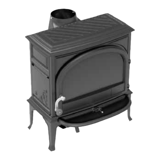
- Page 1 Jøtul F 400 ECO Installation & Operating Instructions Keep these instructions for future reference...
-
Page 2: Table Of Contents
Installation ................ 2 THE INSTALLATION INSTRUCTIONS IN THIS MANUAL 1.1. Technical data ............3 APPLY TO THE JØTUL F 400 ECO WOOD HEATER MODEL. 1.2. Dimensions .............. 3 IT HAS BEEN TESTED FOR EMISSIONS AND EFFICIENCY AND COMPLY ACCORDING TO AS/NZS 4012:2014 &... -
Page 3: Technical Data
1.1. Technical data 1.3. Floor Protector Technical data according to AS/NZS 4012 & 4013 Unless the heater will be standing on a heat resistant floor such as a concrete slab with slate or tiles, it will be necessary Max average heat output: 10.6 kW to provide a floor protector (hearth) to install on. -
Page 4: Positioning The Heater
Fig. 2 Wall Clearances 1.4. Positioning the heater The Jotul F 400 ECO comes with an OPTIONAL REAR HEAT SHIELD that can be fitted to the rear of the heater to offer improved clearances to combustible surfaces. If the heater is being installed adjacent to a non-combustible wall, then the rear heat shield is not required. -
Page 5: Installing The Flue
1.5. Installing the flue 1.7. Installation The flue system used when installing the heater MUST comply Fig. 4 Assemble the door handle with the current installation standard AS/NZS 2918. Full instructions on the installation of the flue will be supplied with the flue kit. -
Page 6: Fitting The Flue Pipe
Fig. 6a Switch from top outlet to rear outlet 1.8. Fitting the flue pipe The product is assembled for a top outlet as standard. Fig. 7 Assembling the flue pipe Unscrew the 2 screws with nuts on the back. Rotate the smoke outlet 180 degrees. Fig. - Page 7 Fig. 8c Through the floor and basement The amount of combustion air for Jøtul’s products is approximately 20-40 m /h. The outside air connection may be fitted directly to the Jøtul F 400 ECO through: • the bottom • through a flexible supply hose from the outside/chimney (only if the chimney has it’s own...
-
Page 8: Location Of Compliance Label
Fig. 9b Fig. 11 The Jøtul F 400 ECO is equipped with the following operating options: Place the external air supply connection (Ø 80mm) with the hose clamp on the outside air hole. Tighten with screw driver. 1.10. Location of compliance label Fig. -
Page 9: Operating
2.2. Using the fireplace for the first time 2. Operating When the fireplace is used for the first time, it may emit an irritating gas which may smell slightly. This happens because WARNING: ANY MODIFICATION OF THE APPLIANCE THAT the paint dries. The gas is not toxic, but the room should be HAS NOT BEEN APPROVED IN WRITING BY THE TESTING thoroughly ventilated. -
Page 10: Adding Firewood
Fig. 13 Be especially careful never to lay a fire using any of the following materials: • Household waste, plastic bags, etc. • Painted or impregnated wood (highly toxic). • Chipboard or laminated boards. • Driftwood (seawater). This may harm the product and pollute the atmosphere. Never use combustible liquids such as petrol, kerosene, alcohol or similar to start the fire. -
Page 11: Maintenance
Fig. 15 Ash pan 3. Maintenance 3.1. Cleaning the glass The product is equipped with an air wash for the glass. Air is sucked in through the air vent on the top of the product and down along the inside of the glass. However, some soot will always stick to the glass, but the quantity will depend on the local draught conditions and adjustment of the air vent. -
Page 12: Inspection Of The Fireplace
4) Check the inside of the flue with the mirror and torch. 4. Servicing 5) Repeat cleaning process if necessary. 6) Once the flue is clean, remove any excess creosote from Any unauthorised modifications to the product are prohibited! the firebox. Only original spare parts may be used! 7) Replace the baffle. -
Page 13: Replacing The Burn Plates
Fig. 18b Removing the baffle plate Fig. 19b 2. The baffle plate loosens in the rear and can be lifted out. 3. When refitting, follow the same procedure in reverse 4. The side burn plates (A) are supplied with insulation mat order. -
Page 14: Replacing The Ash Grate
Fig. 20c 4.3. Replacing the ash grate Fig. 21 3. Remove the old cement (A) from the cement groove. 4. Apply new cement (A) in the cement grooves. Fig. 20d 1. Tilt up the ash grate that loosely sits in the bottom plate of the stove. -
Page 15: Troubleshooting
2. The position of the air control handle is highlighted in 5. Troubleshooting the figure. Tip: If handle seems loose, check the air slide plate to see if it is positioned correctly. 5.1. Poor draught Fig. 22c Check the length of the chimney and that it complies with national laws and regulations. -
Page 16: Guarantee Terms
6. Guarantee terms 7. Manufacturer/Distributor Our guarantee covers: Manufactured by: Jøtul AS guarantees that the external cast-iron parts are free Jøtul AS from defects in materials or manufacturing at the time of N-1602 Fredrikstad purchase. The guarantee on the external cast-iron parts is 10 years from the date of delivery of the heater.
Need help?
Do you have a question about the F 400 ECO and is the answer not in the manual?
Questions and answers