Table of Contents
Advertisement
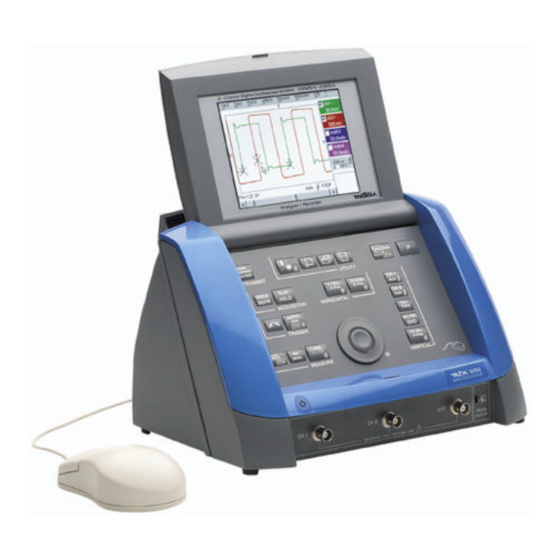
mtx
mtx
3252 Monochrome -
3252
6
0
M
H
z
6
0
M
H
z
6
0
M
H
z
mtx
mtx
3352 Monochrome -
3352
1
0
0
M
H
z
1
0
0
M
H
z
1
0
0
M
H
z
Copyright ©
T
w
o
-
c
h
a
n
n
e
l
T
w
o
-
c
h
a
n
n
e
l
T
w
o
-
c
h
a
n
n
e
l
T
w
o
-
c
h
a
n
n
e
l
T
w
o
-
c
h
a
n
n
e
l
T
w
o
-
c
h
a
n
n
e
l
O
p
e
r
a
t
i
n
g
I
n
s
t
r
u
O
p
e
r
a
t
i
n
g
I
n
s
t
r
u
O
p
e
r
a
t
i
n
g
I
n
s
t
r
Pôle Test et Mesure de CHAUVIN-ARNOUX
F - 74943 ANNECY-LE-VIEUX Cedex
Tel. +33 (0)4.50.64.22.22 - Fax +33 (0)4.50.64.22.00
3252
3252
mtx
mtx
3252-C Colour
3252-C
d
i
g
i
t
a
l
o
s
c
i
l
l
o
d
i
g
i
t
a
l
o
s
c
i
l
l
o
d
i
g
i
t
a
l
o
s
c
i
l
l
o
3352
3352
mtx
mtx
3352-C Colour
3352-C
d
i
g
i
t
a
l
o
s
c
i
l
l
o
d
i
g
i
t
a
l
o
s
c
i
l
l
o
d
i
g
i
t
a
l
o
s
c
i
l
l
o
c
t
i
o
n
s
c
t
i
o
n
s
u
c
t
i
o
n
s
Parc des Glaisins - B. P. 330
6, avenue du Pré de Challes
X02414A00 - Ed. 1 - 01/03
s
c
o
p
e
s
s
c
o
p
e
s
s
c
o
p
e
s
s
c
o
p
e
s
s
c
o
p
e
s
s
c
o
p
e
s
Advertisement
Table of Contents


Need help?
Do you have a question about the MTX 3352 and is the answer not in the manual?
Questions and answers