Sign In
Upload
Download
Table of Contents
Contents
Add to my manuals
Delete from my manuals
Share
URL of this page:
HTML Link:
Bookmark this page
Add
Manual will be automatically added to "My Manuals"
Print this page
×
Bookmark added
×
Added to my manuals
Manuals
Brands
Yamaha Manuals
Motorcycle
NMAX 2016
Owner's manual
Yamaha NMAX 2016 Owner's Manual
Hide thumbs
1
2
3
4
Table Of Contents
5
6
7
8
9
10
11
12
13
14
15
16
17
18
19
20
21
22
23
24
25
26
27
28
29
30
31
32
33
34
35
36
37
38
39
40
41
42
43
44
45
46
47
48
49
50
51
52
53
54
55
56
57
58
59
60
61
62
63
64
65
66
67
68
69
70
71
72
73
74
75
76
77
78
79
80
81
82
83
84
85
86
87
88
89
90
91
92
93
94
page
of
94
Go
/
94
Contents
Table of Contents
Troubleshooting
Bookmarks
Table of Contents
Table of Contents
Safety Information
Further Safe-Riding Points
Description
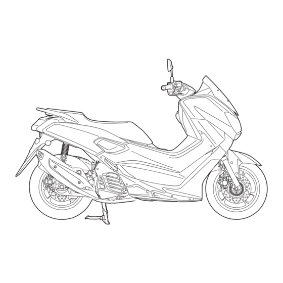
Left View
Right View
Controls and Instruments
Instrument and Control Functions
Main Switch/Steering Lock
Keyhole Shutter
Indicator Lights and Warning Lights
Multi-Function Meter Unit
Handlebar Switches
Front Brake Lever
Rear Brake Lever
Abs
Fuel Tank Cap
Fuel
Fuel Tank Overflow Hose
Catalytic Converter
Seat
Storage Compartments
Sidestand
Ignition Circuit Cut-Off System
For Your Safety - Pre-Operation Checks
Operation and Important Riding Points
Starting the Engine
Starting off
Acceleration and Deceleration
Braking
Tips for Reducing Fuel Consumption
Engine Break-In
Parking
Periodic Maintenance and Adjustment
Owner's Tool Kit
Periodic Maintenance Chart for the Emission Control System
General Maintenance and Lubrication Chart
Removing and Installing Panels
Checking the Spark Plug
Engine Oil and Oil Strainer
Final Transmission Oil
Coolant
Air Filter and V-Belt Case Air Filter Elements
Checking the Throttle Grip Free Play
Valve Clearance
Tires
Cast Wheels
Checking the Front and Rear
Brake Lever Free Play
Checking the Front and Rear Brake Pads
Checking the Brake Fluid Level
Changing the Brake Fluid
Checking the V-Belt
Checking and Lubricating the Cables
Checking and Lubricating the Throttle Grip and Cable
Lubricating the Front and Rear Brake Levers
Checking and Lubricating the Centerstand and Sidestand
Checking the Front Fork
Checking the Steering
Checking the Wheel Bearings
Battery
Replacing the Fuses
Headlight
Replacing an Auxiliary Light Bulb
Brake Light
Replacing the Taillight Bulb
Replacing a Front Turn Signal Light Bulb
Replacing a Rear Turn Signal Light Bulb
Troubleshooting
Troubleshooting Charts
Scooter Care and Storage
Matte Color Caution
Care
Storage
Specifications
Consumer Information
Identification Numbers
Diagnostic Connector
Vehicle Data Recording
Index
Advertisement
Quick Links
1
Table of Contents
2
Valve Clearance
3
Specifications
Download this manual
OWNER'S MANUAL
NMAX
NMAX 150
MOTORCYCLE
Read this manual carefully before oper-
ating this vehicle.
GPD125-A
GPD150-A
BV3-F8199-E1
Table of
Contents
Previous
Page
Next
Page
1
2
3
4
5
Advertisement
Table of Contents
Troubleshooting
Troubleshooting
79
Troubleshooting charts
80
Need help?
Do you have a question about the NMAX 2016 and is the answer not in the manual?
Ask a question
Questions and answers
Related Manuals for Yamaha NMAX 2016
Motorcycle Yamaha Neo's YN50 Owner's Manual
(72 pages)
Motorcycle Yamaha NMAX Owner's Manual
(267 pages)
Motorcycle Yamaha NMAX 155 Owner's Manual
(108 pages)
Motorcycle Yamaha Nouv AT135 Owner's Manual
(84 pages)
Motorcycle Yamaha NVX GDR155 Owner's Manual
(114 pages)
Motorcycle Yamaha MXT9L 2019 Manual
(116 pages)
Motorcycle Yamaha NIKEN 2019 Owner's Manual
(116 pages)
Motorcycle Yamaha NIKEN GT 2021 Owner's Manual
(116 pages)
Motorcycle Yamaha NMAX 2025 Owner's Manual
(138 pages)
Motorcycle Yamaha NIKEN GT 2023 Owner's Manual
(138 pages)
Motorcycle Yamaha MTN1000 2016 Service Manual
(658 pages)
Motorcycle Yamaha FZ-07 2016 Owner's Manual
(112 pages)
Motorcycle Yamaha YZ250F 2016 Owner's Service Manual
(356 pages)
Motorcycle Yamaha WR250F 2016 Owner's Service Manual
(428 pages)
Motorcycle Yamaha Tmax XP500 2016 Owner's Manual
(110 pages)
Motorcycle Yamaha MT-07 2016 Owner's Manual
(102 pages)
This manual is also suitable for:
Nmax 150 2016
Gpd125-a 2016
Gpd150-a 2016
Table of Contents
Save PDF
Print
Rename the bookmark
Delete bookmark?
Delete from my manuals?
Login
Sign In
OR
Sign in with Facebook
Sign in with Google
Upload manual
Upload from disk
Upload from URL


Need help?
Do you have a question about the NMAX 2016 and is the answer not in the manual?
Questions and answers