
Related Manuals for Yamaha FZ-07 2016


Summary of Contents for Yamaha FZ-07 2016
- Page 1 Read this manual carefully before operating this vehicle. OWNER’S MANUAL FZ07H FZ07AH BU2-28199-70...
- Page 2 EAU46093 Read this manual carefully before operating this vehicle. This manual should stay with this vehicle if it is sold.
- Page 3 Yamaha has met these standards without reducing the performance or economy of operation of the motorcycle. To maintain these high standards, it is important that you and your Yamaha dealer pay close attention to the recommended maintenance schedules and operating instructions contained within this manual.
- Page 4 Important manual information EAU10134 Particularly important information is distinguished in this manual by the following notations: This is the safety alert symbol. It is used to alert you to potential personal injury hazards. Obey all safety messages that follow this symbol to avoid possible injury or death.
- Page 5 Important manual information EAU10201 FZ07H / FZ07AH OWNER’S MANUAL ©2016 by Yamaha Motor Co., Ltd. 1st edition, October 2016 All rights reserved. Any reprinting or unauthorized use without the written permission of Yamaha Motor Co., Ltd. is expressly prohibited. Printed in Japan.
-
Page 6: Table Of Contents
Table of contents Location of important labels... 1-1 Sidestand ........4-22 Adjusting the clutch lever free Ignition circuit cut-off system ..4-22 play..........7-20 Safety information......2-1 Auxiliary DC connector ....4-24 Checking the brake lever free play..........7-20 Description ........3-1 For your safety – pre-operation Brake light switches ..... - Page 7 Troubleshooting ......7-42 Troubleshooting charts ....7-43 Motorcycle care and storage ..8-1 Matte color caution ......8-1 Care ..........8-1 Storage ..........8-3 Specifications........9-1 Consumer information ....10-1 Identification numbers....10-1 Diagnostic connector ....10-3 Maintenance record ......10-4 YAMAHA MOTOR CANADA LTD. MOTORCYCLE WARRANTY GUIDE ........10-6 Index ..........11-1...
-
Page 8: Location Of Important Labels
Read and understand all of the labels on your vehicle. They contain important information for safe and proper operation of your vehicle. Never remove any labels from your vehicle. If a label becomes difficult to read or comes off, a replacement label is available from your Yamaha dealer. 2,3,4,5... - Page 9 Location of important labels WARNING WARNING Improper loading can cause loss of control. BEFORE YOU OPERATE THIS VEHICLE, READ Read owner’s manual for proper loading. THE OWNER’S MANUAL AND ALL LABELS. ALWAYS WEAR AN APPROVED MOTORCYCLE 3JJ-28446-A1 HELMET, eye protection, and protective clothing. 1TP-2118K-A1 AVERTISSEMENT LOAD LIMIT...
- Page 10 Location of important labels AVERTISSEMENT LIRE LE MANUEL DU PROPRIETAIRE AINSI QUE TOUTES LES ETIQUETTES AVANT D’UTILISER CE VEHICULE. TOUJOURS PORTER UN CASQUE DE MOTOCYCLISTE APPROUVE, des lunettes et des vêtements de protection. 1TP-2118K-B1 INFORMATION SUR LES PNEUS La pression des pneus à froid doit normalement CAN ICES-2 / NMB-2 être réglée comme suit.
-
Page 11: Safety Information
Safety information Never operate a motorcycle with- pears to be very effective in reduc- EAU1028B out proper training or instruction. ing the chance of this type of Take a training course. Beginners accident. Be a Responsible Owner should receive training from a cer- Therefore: As the vehicle’s owner, you are re- tified instructor. - Page 12 Safety information Many accidents involve inexperi- • Always signal before turning or Protective Apparel enced operators. In fact, many op- changing lanes. Make sure that The majority of fatalities from motorcy- erators who have been involved in other motorists can see you. cle accidents are the result of head in- ...
- Page 13 Safety information Do not run engine outdoors where Avoid Carbon Monoxide Poisoning When loading within this weight limit, All engine exhaust contains carbon engine exhaust can be drawn into keep the following in mind: Cargo and accessory weight monoxide, a deadly gas.
- Page 14 Yamaha accessories, which are avail- performed to your vehicle that change able only from a Yamaha dealer, have any of the vehicle’s design or operation should be kept to a minimum. been designed, tested, and approved characteristics can put you and others •...
- Page 15 Safety information Check that the fuel cock (if operator and may limit control ability, therefore, such accesso- equipped) is in the “OFF” position ries are not recommended. and that there are no fuel leaks. Use caution when adding electri- ...
-
Page 16: Description
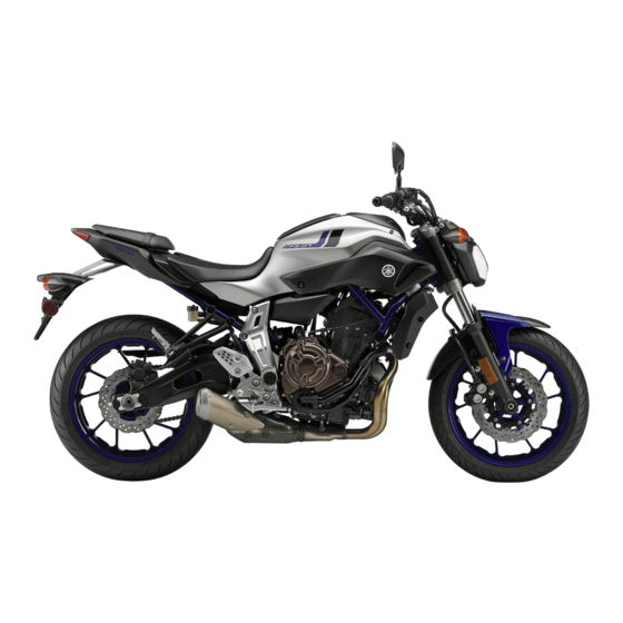
Description EAU10411 Left view 1. Seat lock (page 4-17) 9. Coolant reservoir (page 7-13) 2. Storage compartment (page 4-19) 3. Owner’s tool kit (page 7-2) 4. Shift pedal (page 4-12) 5. Engine oil filler cap (page 7-10) 6. Engine oil drain bolt (page 7-10) 7. -
Page 17: Right View
Description EAU10421 Right view 1. Fuses (page 7-32) 9. Rear brake fluid reservoir (page 7-22) 2. Battery (page 7-31) 3. Shock absorber assembly spring preload adjusting ring (page 4-20) 4. Fuel tank cap (page 4-14) 5. Headlight (page 7-34) 6. Coolant drain bolt (page 7-14) 7. -
Page 18: Controls And Instruments
Description EAU10431 Controls and instruments 1. Clutch lever (page 4-11) 2. Left handlebar switches (page 4-10) 3. Multi-function meter unit (page 4-4) 4. Main switch/steering lock (page 4-1) 5. Front brake fluid reservoir (page 7-22) 6. Right handlebar switches (page 4-10) 7. -
Page 19: Instrument And Control Functions
Instrument and control functions To lock the steering EAU10462 Main switch/steering lock The headlight comes on automatically when the engine is started and stays on until the key is turned to “OFF”, even if the engine stalls. EAU10662 All electrical systems are off. The key can be removed. -
Page 20: Indicator Lights And Warning Lights
If the warning light does not come on moved. initially when the key is turned to “ON”, The steering must be locked before the EAU11032 have a Yamaha dealer check the elec- Turn signal indicator lights “ ” key can be turned to “ ”. - Page 21 Instrument and control functions If the oil level is below the minimum The electrical circuit of the warning have a Yamaha dealer check the self- level, add sufficient oil of the recom- light can be checked by turning the key diagnosis system.
-
Page 22: Multi-Function Meter Unit
does not go off after traveling at a speed of 10 km/h (6 mi/h) or high- The ABS may not work correctly. If any of the above occurs, have a Yamaha dealer check the system as soon as possible. (See page 4-13 for an expla- 1. - Page 23 Instrument and control functions Tachometer Clock EWA12423 WARNING Be sure to stop the vehicle before making any setting changes to the multi-function meter unit. Changing settings while riding can distract the operator and increase the risk of an accident. Except when accessing the brightness 1.
- Page 24 Fuel meter Travel at a constant speed. warning indicator will flash repeatedly. Select the transmission gear that If this occurs, have a Yamaha dealer check the vehicle. is appropriate for the vehicle speed. Eco indicator Transmission gear display 1.
- Page 25 Instrument and control functions Multi-function display stantaneous fuel consumption “km/L” or “L/100 km”, average fuel consump- The odometer will lock at 999999. tion “AVE_ _._ km/L” or “AVE_ _._ The tripmeters will lock at 9999.9 L/100 km”, coolant temperature “_ _ but can be manually reset.
- Page 26 Instrument and control functions You can manually reset the fuel re- “L/100 km”: The amount of fuel The average fuel consumption can be serve tripmeter, or after refueling necessary to travel 100 km under set to either “AVE_ _._ km/L” or “AVE_ and traveling 5 km (3 mi) it will re- the current riding conditions is _._ L/100 km”.
- Page 27 The accuracy of the temperature note the code number and have a below 40 °C, “LO” will be dis- reading may be affected by engine Yamaha dealer check the vehicle. played. heat when riding slowly (under 20 ECA11591 The coolant temperature varies...
-
Page 28: Handlebar Switches
Instrument and control functions Brightness control mode EAU1234M EAU12352 Handlebar switches Pass switch “ ” Press this switch to flash the headlight. Left When the dimmer switch is set to “ ”, the passing switch has no ef- fect. EAU12401 Dimmer switch “... -
Page 29: Clutch Lever
Instrument and control functions EAU68270 ECA10062 EAU12822 Start/Engine stop switch “ / ” Clutch lever NOTICE To crank the engine with the starter, Do not use the hazard lights for an set this switch to “ ”, and then slide extended length of time with the en- the switch toward “... -
Page 30: Shift Pedal
Instrument and control functions EAU12872 EAU26825 EAU12944 Shift pedal Brake lever Brake pedal The brake lever is located on the right side of the handlebar. To apply the front brake, pull the lever toward the throttle grip. 1. Shift pedal 1. -
Page 31: Abs (For Abs Models)
Instrument and control functions EAU60021 ABS (for ABS models) The ABS performs a self-diagno- The Yamaha ABS (Anti-lock Brake sis test each time the vehicle first System) features a dual electronic con- starts off after the key is turned to trol system, which acts on the front and “ON”... -
Page 32: Fuel Tank Cap
Instrument and control functions EAU13075 EAU13222 Fuel tank cap Fuel The fuel tank cap cannot be closed un- Make sure there is sufficient gasoline in less the key is in the lock. In addition, the tank. the key cannot be removed if the cap is EWA10882 WARNING not properly closed and locked. - Page 33 EWA15152 as well as to the exhaust system. WARNING Gasoline is poisonous and can cau- Your Yamaha engine has been de- se injury or death. Handle gasoline signed to use regular unleaded gaso- with care. Never siphon gasoline by line with a pump octane number mouth.
-
Page 34: Fuel Tank Breather Hose And Overflow Hose
Instrument and control functions EAU55512 EAU13434 ECA10702 Fuel tank breather hose and Catalytic converter NOTICE overflow hose This model is equipped with a catalytic Use only unleaded gasoline. The use converter in the exhaust system. of leaded gasoline will cause unre- EWA10863 pairable damage to the catalytic WARNING... -
Page 35: Seats
Instrument and control functions To install the passenger seat EAU59901 Seats 1. Insert the projections on the front of the passenger seat into the seat Passenger seat holders as shown, and then push the rear of the seat down to lock it To remove the passenger seat in place. -
Page 36: Helmet Holding Cable
Instrument and control functions To install the rider seat EAU59981 Helmet holding cable 1. Fit the slot in the seat onto the pro- When removing the screwdriver, slide A helmet holding cable is located on jection on the frame cross mem- the screwdriver toward the “... -
Page 37: Storage Compartment
Instrument and control functions To release a helmet from the helmet EAU14465 Storage compartment holding cable Make sure that the screwdriver is se- 1. Remove the passenger seat. curely positioned between its holders, 2. Remove the screwdriver, then re- and then position the cable loops to- move the helmet holding cable ward the middle of the screwdriver be- from the helmet. -
Page 38: Adjusting The Shock Absorber Assembly
Instrument and control functions Do not exceed the maximum EAU47001 Adjusting the shock absorber load of 172 kg (379 lb) (FZ07AH) assembly 175 kg (386 lb) (FZ07H) for the This shock absorber assembly is vehicle. equipped with a spring preload adjust- ing ring. -
Page 39: Luggage Strap Holders
Do not dispose of a damaged or 2. Hook worn-out shock absorber as- sembly yourself. Take the shock absorber assembly to a Yamaha dealer for any service. 1. Luggage strap holder There are six luggage strap holders, four on the bottom of the passenger seat and one on each passenger foot- rest. -
Page 40: Sidestand
EAU15306 EAU68280 Sidestand Ignition circuit cut-off system Yamaha dealer repair it if it does not The sidestand is located on the left The ignition circuit cut-off system function properly. side of the frame. Raise the sidestand... - Page 41 Instrument and control functions WARNING With the engine turned off: 1. Move the sidestand down. If a malfunction is noted, have a Yamaha 2. Make sure that the start/engine stop switch is set to “ ”. dealer check the system before riding.
-
Page 42: Auxiliary Dc Connector
Instrument and control functions EAU70641 Auxiliary DC connector This vehicle is equipped with an auxil- iary DC connector. Consult your Yamaha dealer before installing any accessories. 4-24... -
Page 43: For Your Safety - Pre-Operation Checks
• If necessary, add recommended coolant to specified level. 7-13 • Check cooling system for leakage. • Check operation. • If soft or spongy, have Yamaha dealer bleed hydraulic system. • Check brake pads for wear. Front brake • Replace if necessary. - Page 44 • Make sure that operation is smooth. • Check throttle grip free play. Throttle grip 7-16, 7-27 • If necessary, have Yamaha dealer adjust throttle grip free play and lubricate ca- ble and grip housing. • Make sure that operation is smooth. Control cables 7-26 •...
- Page 45 • Tighten if necessary. Instruments, lights, signals • Check operation. — and switches • Correct if necessary. • Check operation of ignition circuit cut-off system. Sidestand switch 4-22 • If system is not working correctly, have Yamaha dealer check vehicle.
-
Page 46: Operation And Important Riding Points
a lean angle sensor to stop the en- The transmission is in the neutral understand, ask your Yamaha dealer. gine in case of a turnover. In this EWA10272 position. -
Page 47: Shifting
The neutral indi- cator light should come on. If not, page 4-2 for the corresponding warning light circuit check. ask a Yamaha dealer to check the After going off once, the oil electrical circuit. pressure warning... - Page 48 Operation and important riding points 4. At the recommended shift points clutch lever in, use the brakes to ECA10261 NOTICE shown in the following table, close slow the motorcycle, and continue Even with the transmission in the throttle, and at the same time, to downshift as necessary.
-
Page 49: Engine Break-In
1600 km (1000 mi). The various parts in period, immediately have a 5th → 6th: 60 km/h (37 mph) the engine wear and polish themselves Yamaha dealer check the vehi- Shift down points: to the correct operating clearances. cle. 6th → 5th: 45 km/h (28 mph) During this period, prolonged full-throt- 5th →... -
Page 50: Parking
Operation and important riding points EAU17214 Parking When parking, stop the engine, and then remove the key from the main switch. EWA10312 WARNING Since the engine and exhaust system can become very hot, park in a place where pedestri- ans or children are not likely to touch them and be burned. - Page 51 To avoid possible burns, let tivities incorrectly may increase brake components cool before your risk of injury or death during touching them. service or while using the vehicle. If you are not familiar with vehicle ser- vice, have a Yamaha dealer perform service.
-
Page 52: Owner's Tool Kit
Owner’s tool kit If you do not have the tools or experi- ence required for a particular job, have a Yamaha dealer perform it for you. 1. Owner’s tool kit The owner’s tool kit is located under the passenger seat. Some tools are also located on the bottom of the pas- senger seat. -
Page 53: Periodic Maintenance Chart For The Emission Control System
From 37000 km (24000 mi) or 36 months, repeat the maintenance intervals starting from 13000 km (8000 mi) or 12 months. Items marked with an asterisk require special tools, data and technical skills, have a Yamaha dealer perform the ser- vice. -
Page 54: General Maintenance And Lubrication Chart
24 months 30 months • Perform dynamic inspection us- Diagnostic system √ √ √ √ √ √ ing Yamaha diagnostic tool. check • Check the error codes. Air filter element • Replace. Every 37000 km (24000 mi) √ √ √ √... - Page 55 Periodic maintenance and adjustment INITIAL ODOMETER READINGS 1000 km 7000 km 13000 km 19000 km 25000 km 31000 km ITEM ROUTINE (600 mi) (4000 mi) (8000 mi) (12000 mi) (16000 mi) (20000 mi) 1 month 6 months 12 months 18 months 24 months 30 months •...
- Page 56 Periodic maintenance and adjustment INITIAL ODOMETER READINGS 1000 km 7000 km 13000 km 19000 km 25000 km 31000 km ITEM ROUTINE (600 mi) (4000 mi) (8000 mi) (12000 mi) (16000 mi) (20000 mi) 1 month 6 months 12 months 18 months 24 months 30 months Brake pedal pivot...
- Page 57 • Change coolant. Front and rear √ √ √ √ √ √ 28 * • Check operation. brake switches • Apply Yamaha cable lubricant or √ √ √ √ √ √ 29 * Control cables other suitable cable lubricant thoroughly.
- Page 58 Periodic maintenance and adjustment Hydraulic brake service • After disassembling the brake master cylinders and calipers, always change the fluid. Regularly check the brake fluid levels and fill the reservoirs as required. • Every two years replace the internal components of the brake master cylinders and calipers, and change the brake fluid.
-
Page 59: Checking The Spark Plugs
1/2 turn past finger tight. However, the Yamaha dealer. Since heat and depos- with a wire thickness gauge and, if spark plug should be tightened to the its will cause any spark plug to slowly necessary, adjusted to specification. -
Page 60: Engine Oil And Oil Filter Cartridge
Periodic maintenance and adjustment EAU60472 Engine oil and oil filter car- tridge The engine oil level should be checked before each ride. In addition, the oil must be changed and the oil filter car- tridge replaced at the intervals speci- fied in the periodic maintenance and lubrication chart. - Page 61 Periodic maintenance and adjustment An oil filter wrench is available at a Yamaha dealer. 6. Apply a thin coat of clean engine oil to the O-ring of the new oil filter cartridge. 1. Engine oil drain bolt 1. Torque wrench 2.
- Page 62 2.30 L (2.43 US qt, 2.02 Imp.qt) is correct, immediately turn the en- With oil filter removal: gine off and have a Yamaha dealer 2.60 L (2.75 US qt, 2.29 Imp.qt) check the vehicle. 13. Turn the engine off, wait a few mi-...
-
Page 63: Coolant
2. Check the coolant level in the corrosion. If water has been coolant reservoir. added to the coolant, have a Yamaha dealer check the anti- The coolant should be between the mi- freeze content of the coolant as nimum and maximum level marks. - Page 64 Periodic maintenance and adjustment soon as possible, otherwise the 5. Remove the coolant reservoir cap. effectiveness of the coolant will be reduced. [ECA10473] Coolant reservoir capacity (up to the maximum level mark): 0.25 L (0.26 US qt, 0.22 Imp.qt) EAU59863 To change the coolant 1.
- Page 65 Antifreeze/water mixture ratio: its gasket to drain the coolant from the vehicle for coolant leakage. If the cooling system. coolant is leaking, have a Yamaha Recommended antifreeze: High-quality ethylene glycol anti- dealer check the cooling system. freeze containing corrosion inhibi-...
-
Page 66: Replacing The Air Filter Element And Cleaning The Check Hose
1. Remove the air filter check hose Throttle grip free play: 3.0–5.0 mm (0.12–0.20 in) under the air filter case. Periodically check the throttle grip free play and, if necessary, have a Yamaha dealer adjust it. 1. Air filter check hose 7-16... -
Page 67: Valve Clearance
Tire air pressure (measured on cold from occurring, the valve clearance small area of road contact. Therefore, it tires): must be adjusted by a Yamaha dealer is essential to maintain the tires in good Front: 225 kPa (2.25 kgf/cm², 33 psi) - Page 68 “broken used or have only been used occasion- wall is cracked, have a Yamaha dealer in” for it to develop its optimal ally. Cracking of the tread and sidewall replace the tire immediately.
-
Page 69: Cast Wheels
If any damage is found, have high-speed ride. high speeds. a Yamaha dealer replace the Brand-new tires can have a rel- After extensive tests, only the tires list- wheel. Do not attempt even the... -
Page 70: Adjusting The Clutch Lever Free Play
There should be no free play at the 1. Clutch lever free play adjusting bolt brake lever end. If there is free play, 2. Clutch lever free play have a Yamaha dealer inspect the brake system. Clutch lever free play: EWA14212 5.0–10.0 mm (0.20–0.39 in) -
Page 71: Brake Light Switches
The brake light, which is activated by the brake pedal and brake lever, should come on just before braking takes effect. If necessary, have a Yamaha dealer adjust the brake light switches. 1. Rear brake light switch 2. Rear brake light switch adjusting nut... -
Page 72: Checking The Front And Rear Brake Pads
EAU22393 EAU40262 Checking the front and rear Checking the brake fluid level Yamaha dealer replace the brake pads brake pads Before riding, check that the brake fluid as a set. is above the minimum level mark. - Page 73 Use only the specified brake flu- Rear brake fluid level goes down suddenly, have a id; otherwise, the rubber seals Yamaha dealer check the cause before further riding. may deteriorate, causing leak- age. Refill with the same type of brake fluid.
-
Page 74: Changing The Brake Fluid
Periodic maintenance and adjustment EAU22733 EAU22762 Changing the brake fluid Drive chain slack Have a Yamaha dealer change the The drive chain slack should be brake fluid at the intervals specified in checked before each ride and adjusted the periodic maintenance and lubrica- if necessary. - Page 75 3. Tighten the axle nut, and then EAU59921 To adjust the drive chain slack tighten the locknuts to the speci- Consult a Yamaha dealer before ad- fied torques. justing the drive chain slack. 1. Loosen the locknut at each end of...
-
Page 76: Cleaning And Lubricating The Drive Chain
If a cable is wet areas. Service the drive chain as damaged or does not move smoothly, follows. have a Yamaha dealer check or re- place it. WARNING! Damage to the ECA10584 NOTICE outer housing of cables may result... -
Page 77: Checking And Lubricating The Throttle Grip And Cable
In pedals should be checked before each addition, the cable should be lubricat- ride, and the pedal pivots should be lu- ed by a Yamaha dealer at the intervals bricated if necessary. specified in the periodic maintenance Brake pedal chart. -
Page 78: Checking And Lubricating The Brake And Clutch Levers
EWA10732 Clutch lever WARNING If the sidestand does not move up and down smoothly, have a Yamaha dealer check or repair it. Otherwise, the sidestand could contact the ground and distract the operator, re- sulting in a possible loss of control. -
Page 79: Lubricating The Rear Suspension
The swingarm pivots must be lubricat- ce and hold it in an upright posi- sion must be lubricated by a Yamaha ed by a Yamaha dealer at the intervals tion. WARNING! To avoid injury, dealer at the intervals specified in the... -
Page 80: Checking The Steering
[EWA10752] the periodic maintenance and lubrica- 2. Hold the lower ends of the front have a Yamaha dealer check or re- tion chart. If there is play in the wheel fork legs and try to move them for- pair it. -
Page 81: Battery
Electrolyte is poisonous and 3. Fully charge the battery before installation. NOTICE: When in- Have a Yamaha dealer charge the bat- dangerous since it contains sul- tery as soon as possible if it seems to stalling the battery, be sure to furic acid, which causes severe have discharged. -
Page 82: Replacing The Fuses
Periodic maintenance and adjustment connect the positive lead before FZ07H EAU59872 Replacing the fuses connecting the negative lead. The main fuse and the fuse boxes, [ECA16842] which contain the fuses for the individ- 1 2 3 4 5 4. After installation, make sure that ual circuits, are located under the rider the battery leads are properly con- seat. - Page 83 1 2 3 4 5 possibly a fire. 4. If the fuse immediately blows [EWA15132] again, have a Yamaha dealer Specified fuses: check the electrical system. Main fuse: 30.0 A Auxiliary fuse: 2.0 A...
-
Page 84: Replacing The Headlight Bulb
Periodic maintenance and adjustment EAU59881 Replacing the headlight bulb This model is equipped with a halogen bulb headlight. If the headlight bulb burns out, replace it as follows. ECA10651 NOTICE Take care not to damage the follow- ing parts: Headlight bulb 1. -
Page 85: Replacing The Auxiliary Light Bulb
Periodic maintenance and adjustment 7. Have a Yamaha dealer adjust the EAU46405 Replacing the auxiliary light headlight beam if necessary. bulb If the auxiliary light bulb burns out, re- place it as follows. 1. Remove the headlight unit. (See page 7-34.) 2. -
Page 86: Brake/Tail Light
1. Remove the turn signal light unit If the brake/tail light does not come on, by removing the screw. have a Yamaha dealer check it. 1. Auxiliary light bulb 4. Insert a new bulb into the socket. 5. Install the socket (together with the bulb) by turning it clockwise. -
Page 87: Replacing The License Plate Light Bulb
Periodic maintenance and adjustment 6. Install the turn signal light unit by EAU59890 Replacing the license plate installing the screw. NOTICE: Do light bulb not overtighten the screw, oth- 1. Remove the license plate light unit erwise the lens may break. by removing the nuts, washers [ECA11192] and collars, and then remove the... -
Page 88: Supporting The Motorcycle
Supporting the motorcycle Front wheel (for non-ABS models) EWA14841 WARNING For the ABS model, have a Yamaha dealer remove and install the wheel. EAU61492 1. License plate light bulb To remove the front wheel 3. Insert a new bulb into the socket. - Page 89 Periodic maintenance and adjustment 2. Insert the wheel axle from the right side. 3. Lower the front wheel so that it is on the ground, and then put the sidestand down. 4. Install the brake calipers and the reflectors by installing the bolts. Make sure that there is enough space 1.
-
Page 90: Rear Wheel (For Non-Abs Models)
EWA14841 Front wheel axle pinch bolt: WARNING 23 N·m (2.3 kgf·m, 17 lb·ft) For the ABS model, have a Yamaha 8. Push down hard on the handlebar dealer remove and install the wheel. several times to check for proper fork operation. - Page 91 Periodic maintenance and adjustment Make sure that the slot in the brake caliper bracket is fit over the retainer on the swingarm. Make sure that there is enough space between the brake pads before installing the wheel. If the chain puller is removed, make sure that the arrow mark on 1.
-
Page 92: Troubleshooting
However, should your motorcycle 2. Install the drive chain onto the rear require any repair, take it to a Yamaha sprocket. dealer, whose skilled technicians have 3. Install the drive chain slack adjust- the necessary tools, experience, and ing plate, washer and the axle nut. -
Page 93: Troubleshooting Charts
Remove the spark plugs and check the electrodes. The engine does not start. Have a Yamaha dealer check the vehicle. Check the compression. 4. Compression The engine does not start. There is compression. - Page 94 Start the engine. If the engine overheats again, have a The coolant level Yamaha dealer check and repair the cooling system. is OK. If coolant is not available, tap water can be temporarily used instead, provided that it is changed to the recommended cool- ant as soon as possible.
-
Page 95: Motorcycle Care And Storage
Some models are equipped with matte colored finished parts. Be ble. Rust and corrosion can develop Cleaning sure to consult a Yamaha dealer for even if high-quality components are ECA10773 NOTICE used. A rusty exhaust pipe may go un-... - Page 96 Motorcycle care and storage off any detergent residue using shield. Test the product on a plenty of water, as it is harmful small hidden part of the wind- Salt sprayed on roads in the winter to plastic parts. shield to make sure that it does may remain well into spring.
-
Page 97: Storage
EWA11132 poorly ventilated room or cover- WARNING ing it with a tarp, while it is still Consult a Yamaha dealer for ad- Contaminants on the brakes or tires wet, will allow water and humid- can cause loss of control. - Page 98 Motorcycle care and storage 2. Fill up the fuel tank and add fuel e. Remove the spark plug caps stabilizer (if available) to prevent from the spark plugs, and then Make any necessary repairs before the fuel tank from rusting and the install the spark plugs and the storing the motorcycle.
-
Page 99: Specifications
Specifications Dimensions: Compression ratio: Coolant quantity: 11.5 : 1 Overall length: Coolant reservoir (up to the maximum level Starting system: 2085 mm (82.1 in) mark): Electric starter Overall width: 0.25 L (0.26 US qt, 0.22 Imp.qt) Lubrication system: 745 mm (29.3 in) Radiator (including all routes): Wet sump Overall height:... - Page 100 Specifications Secondary reduction ratio: Rear tire: Specified brake fluid: 2.688 (43/16) DOT 4 Type: Transmission type: Rear brake: Tubeless Constant mesh 6-speed Size: Type: Gear ratio: 180/55 ZR 17M/C(73W) Hydraulic single disc brake 1st: Manufacturer/model: Specified brake fluid: 2.846 (37/13) MICHELIN/PILOT ROAD 3A DOT 4 2nd:...
- Page 101 Specifications Battery: Engine trouble warning light: Model: ABS warning light: YTZ10S LED (FZ07AH) Voltage, capacity: Fuse(s): 12 V, 8.6 Ah (10 HR) Headlight: Main fuse: 30.0 A Bulb type: Auxiliary fuse: Halogen bulb 2.0 A Bulb wattage: Headlight fuse: Headlight: 15.0 A H4, 60.0 W/55.0 W Signaling system fuse:...
-
Page 102: Consumer Information
Vehicle identification number ed when registering the vehicle with the authorities in your area and when EAU26442 Engine serial number ordering spare parts from a Yamaha dealer. VEHICLE IDENTIFICATION NUMBER: 1. Vehicle identification number ENGINE SERIAL NUMBER: The vehicle identification number is 1. - Page 103 This label shows specifica- mation will be needed when ordering key. tions related to exhaust emissions as spare parts from a Yamaha dealer. required by federal law, state law and Environment Canada. 10-2...
-
Page 104: Diagnostic Connector
Consumer information EAU69910 Diagnostic connector 1. Diagnostic connector The diagnostic connector is located as shown. 10-3... -
Page 105: Maintenance Record
Consumer information EAU26643 Maintenance record Copies of work orders and/or receipts for parts purchased and installed on your vehicle will be required to document that maintenance has been completed in accordance with the emissions warranty. The chart below is printed only as a reminder that maintenance work is required. - Page 106 Consumer information Maintenance Date of Servicing dealer Mileage Remarks interval service name and address 55000 km (36000 mi) or 54 months 61000 km (40000 mi) or 60 months 10-5...
-
Page 107: Yamaha Motor Canada Ltd
In this warranty, the term ‘MOTORCYCLE’ shall refer to a new or YZ, with the exception of WR25R, WR25X and YZ85 change of registration is sent to YAMAHA at the time of such motorcycle manufactured by YAMAHA MOTOR COMPANY, LTD. - Page 108 CUSTOMER at the time of DELIVERY. fitness for a particular purpose on the part of YAMAHA, and any other obligation or liability on behalf of YAMAHA, and the above...
-
Page 109: Index
Index Maintenance, emission control system ..........7-3 ABS (for ABS models) ......4-13 Engine break-in ........6-4 Maintenance record......10-4 ABS warning light (for ABS models) ..4-3 Engine oil and oil filter cartridge... 7-10 Matte color, caution........ 8-1 Air filter element and check hose, Engine serial number ...... - Page 110 Index Throttle grip and cable, checking and lubricating...........7-27 Throttle grip free play, checking ...7-16 Tires ............7-17 Tool kit ............7-2 Troubleshooting ........7-42 Troubleshooting charts......7-43 Turn signal indicator lights......4-2 Turn signal light bulb, replacing....7-36 Turn signal switch .........4-10 Valve clearance........7-17 Vehicle Emission Control Information label ............10-2 Vehicle identification number ....10-1 Warranty ..........10-6...
- Page 111 Yamalube – Take care of your Yamaha with legendary Yamalube oils, lubricants, and care products. They’re formulated and approved by the toughest judges we know: the Yamaha engineering teams that know your Yamaha from the inside out.
- Page 112 PRINTED ON RECYCLED PAPER PRINTED IN JAPAN 2016.11-0.5×1 CR...
Need help?
Do you have a question about the FZ-07 2016 and is the answer not in the manual?
Questions and answers