Advertisement
Available languages
Available languages
Table of Contents
- 1 Operating Instructions
- 2 Cutting with the Plunge Base (Fig. 8)
- 3 Installing and Removing the Dust Extraction Hood (Fig. 4)
- 4 Adjustments
- 5 Adjusting the Depth of Cut (Fig. 5, 6, and 7)
- 6 Functional Description
- 7 Assembly
- 8 Installing and Removing the Plunge Base (Fig. 2 and 3)
- Download this manual
FT421
Model:
Modelo:
Modèle:
PLUNGE BASE
BASE POUR COUPE EN PLONGÉE
BASE DE INMERSIÓN
To reduce the risk of injury, the user must read and understand
WARNING
the operator's manual before using this product. Save these
instructions together with the trim router manual for future reference.
This plunge base is designed to only be used with FLEX FX4221
WARNING
trim router.
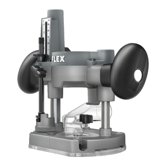
FUNCTIONAL DESCRIPTION
Fig. 1
Depth Gauge
Depth
Gauge
Indicator
Handle
Depth
(x2)
Lock Knob
Depth Gauge
Rod
Micro
Adjustment
Sleeve
Stop Turret
Screw Knob
Dust Extraction Hood
ASSEMBLY
Detach the battery pack from the tool before performing any
WARNING
assembly or adjustments, or changing accessories. Such
preventive safety measures reduce the risk of starting the tool accidentally.
INSTALLING AND REMOVING THE
Fig. 2
PLUNGE BASE (FIG. 2 AND 3)
To install the plunge base
1. Unscrew the depth adjustment ring
Motor
and remove it from the motor unit.
Snap the depth adjustment ring onto
Depth
the fixed base, when not in use, to
Adjustment
prevent loss.
Ring
2. Open the lock lever on the plunge base.
3. Align the vertical slot on the motor
unit with the pegs on the inside of the
plunge base.
4. Lower the motor into the plunge base
until the motor is stopped by the motor
stop.
5. Close the lock lever.
To remove the plunge base
1. Open the lock lever on the plunge
base.
2. Pull the motor unit from the plunge
base.
OPERATOR'S MANUAL
MANUAL DEL OPERADOR
MANUEL DE L'UTILISATEUR
INSTALLING AND REMOVING THE DUST
EXTRACTION HOOD (FIG. 4)
The dust extraction hood attaches to the
plunge base for dust free routing when
used in combination with a suitable vacuum
cleaner/dust extractor. The dust extraction
hood allows connection of a 1-1/4" (32 mm)
vacuum hose or adaptor.
To install the dust extraction hood
1. Remove the motor unit from the
plunge base following the section "To
remove the plunge base".
2. Align the pegs on the dust extraction
hood with the slots in the plunge base.
3. Secure the dust extraction hood in place by tightening the screw knob.
To remove the dust extraction hood
1. Fully unscrew the screw knob from the plunge base.
2. Remove the dust extraction hood away from the plunge base.
Plunge Release Lever
WARNING
preventive safety measures reduce the risk of starting the tool accidentally.
ADJUSTING THE DEPTH OF CUT
(FIG. 5, 6, AND 7)
1. Detach the battery pack.
2. Select and install the desired cutter
bit following the instructions in the trim
router manual.
3. Rotate the stop turret until the lowest
turret stop is directly below the depth
gauge rod.
4. Loosen the depth lock knob and slide
the depth gauge rod down so that it
Base Lock Lever
meets the lowest turret stop.
5. Press the plunge release lever and
lower the router motor until the bit
touches the workpiece.
6. Release the plunge release lever.
7. Slide the depth gauge indicator to zero
(0).
8. Raise the depth gauge rod to the
desired depth of cut and tighten the
depth lock knob.
9. Press the plunge release lever and
raise the router motor to prepare for
the cut.
NOTICE: The micro adjustment sleeve is
used for fine adjustments (loosen for a shallower cut, tighten for a deeper cut).
Using the rotating turret for multiple pass cuts
If the depth of cut required is more than the acceptable depth in a single pass, rotate the
stop turret so that the depth gauge rod meets the higher turret stop initially. After each cut,
rotate the stop turret so that the depth gauge meets the lower turret stop until the final
depth is reached.
Fig. 3
Pegs
Fig. 4
ADJUSTMENTS
Detach the battery pack from the tool before performing any
assembly or adjustments, or changing accessories. Such
Fig. 5
b
Plunge
Release
a
Lever
Fig. 6
c
Depth Gauge
Indicator
Depth
Gauge Rod
Stop
Turret
Workpiece
Do not adjust the
WARNING
stop turret while the
router is running. This will place your
hands too near the cutter bit.
Slot
Lock
Lever
Motor
Stop
OPERATING INSTRUCTIONS
CUTTING WITH THE PLUNGE BASE
Screw
(FIG. 8)
Knob
To reduce the risk of
WARNING
injury, never use the
plunge base in a router table.
To reduce the risk of injury, grip both
Dust
of the plunge base handles while
Extraction
operating.
Hood
1. Securely clamp the workpiece.
2. With cutting depth set, press the
plunge release lever and raise the bit
above the workpiece.
3. Hold the router so the bit is away from
you and not in contact with the workpiece.
4. Turn on the tool.
5. Press the plunge release lever and slowly lower the bit into the workpiece until
the depth gauge rod stops on the turret.
6. Release the plunge release lever.
7. Begin moving the router while keeping the subbase flat on the workpiece.
8. W hen finished, press the plunge release lever and raise the bit out of the
workpiece.
9. To stop the motor, hold the router so the bit is away from you and turn off the tool.
10. For multiple pass cuts, rotate the stop turret to the next stop and repeat. Make
multiple passes, rotating the stop turret to a lower stop each time.
Depth
Lock
Knob
Bit
Fig. 7
e
d
Depth
Lock
Knob
Depth
Gauge
Rod
Fig. 8
Advertisement
Table of Contents

Related Manuals for Flex FT421


Summary of Contents for Flex FT421
- Page 1 1. Securely clamp the workpiece. This plunge base is designed to only be used with FLEX FX4221 WARNING 2. Align the pegs on the dust extraction 2.
- Page 2 Cela placerait AVERTISSEMENT fixe à la base pour coupe en plongée afin être utilisée uniquement avec la toupie de finition vos mains trop près de la mèche de l’outil de coupe. à vis de produire un toupillage sans poussière FLEX FX4221. lorsqu’elle est utilisée en combinaison avec un aspirateur/extracteur de poussière INSTRUCTIONS POUR L’UTILISATION DESCRIPTION FONCTIONNELLE approprié. La hotte d’extraction de la Hotte pour poussière permet le raccordement d’un...
- Page 3 Esta base de inmersión está diseñada para utilizarse solo ADVERTENCIA instala en la base de inmersión para fresar tipo con la fresadora recortadora FLEX FX4221. sin dispersar polvo cuando se utiliza en tornillo INSTRUCCIONES DE UTILIZACIÓN combinación con una aspiradora o un DESCRIPCIÓN FUNCIONAL...
Need help?
Do you have a question about the FT421 and is the answer not in the manual?
Questions and answers