Advertisement
Table of Contents
- 1 Table of Contents
- 2 Warning Decal Placement
- 3 Important Precautions
- 4 Before You Begin
- 5 Part Identification Chart
- 6 Assembly
- 7 How to Use the Treadmill
- 8 How to Fold and Move the Treadmill
- 9 Maintenance and Troubleshooting
- 10 Exercise Guidelines
- 11 Part List
- 12 Exploded Drawing
- 13 Ordering Replacement Parts
- 14 Recycling Information
- Download this manual
Model No. NETL19716.0
Serial No.
Write the serial number in the space
above for reference.
Serial
Number
Decal
CUSTOMER SERVICE
UNITED KINGDOM
Call: 0330 123 1045
From Ireland: 053 92 36102
Website: www.iconsupport.eu
E-mail: csuk@iconeurope.com
Write:
ICON Health & Fitness, Ltd.
Unit 1D, The Gateway
Fryers Way, Silkwood Park
OSSETT
WF5 9TJ
UNITED KINGDOM
AUSTRALIA
Call: 1800 993 770
E-mail: australiacc@iconfitness.com
Write:
ICON Health & Fitness
PO Box 635
WINSTON HILLS NSW 2153
AUSTRALIA
CAUTION
Read all precautions and instruc-
tions in this manual before using
this equipment. Save this manual
for future reference.
USER'S MANUAL
www.iconeurope.com
Advertisement
Table of Contents

Related Manuals for NordicTrack C1650


Summary of Contents for NordicTrack C1650
- Page 1 Model No. NETL19716.0 Serial No. USER'S MANUAL Write the serial number in the space above for reference. Serial Number Decal CUSTOMER SERVICE UNITED KINGDOM Call: 0330 123 1045 From Ireland: 053 92 36102 Website: www.iconsupport.eu E-mail: csuk@iconeurope.com Write: ICON Health & Fitness, Ltd. Unit 1D, The Gateway Fryers Way, Silkwood Park OSSETT...
-
Page 2: Table Of Contents
Bluetooth SIG, Inc. and are used under ® license. Wi-Fi is a registered trademark of Wi-Fi Alliance. WPA and WPA2 are trademarks of Wi-Fi Alliance. NORDICTRACK is a registered trademark of ICON Health & Fitness, Inc. -
Page 3: Important Precautions
IMPORTANT PRECAUTIONS WARNING: To reduce the risk of burns, fire, electric shock, or injury to persons, read all important precautions and instructions in this manual and all warnings on your treadmill before using your treadmill. ICON assumes no responsibility for personal injury or property damage sus- tained by or through the use of this product. - Page 4 21. The treadmill is capable of high speeds. 26. Do not change the incline of the treadmill by Adjust the speed in small increments to placing objects under the treadmill. avoid sudden jumps in speed. 27. Never insert any object into any opening on 22.
-
Page 5: Before You Begin
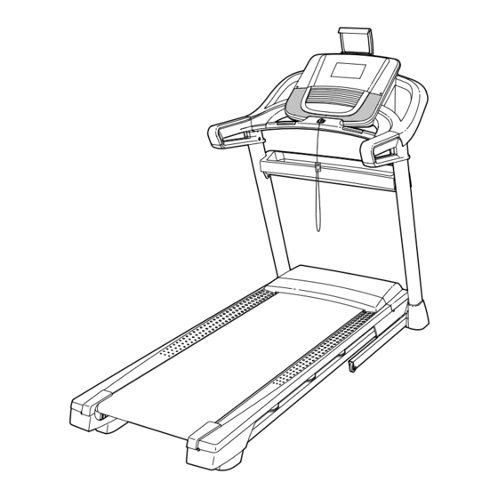
BEFORE YOU BEGIN Thank you for selecting the new NORDICTRACK manual. To help us assist you, note the product model ® C 1650 treadmill. The C 1650 treadmill provides an number and serial number before contacting us. The impressive selection of features designed to make your model number and the location of the serial number workouts at home more effective and enjoyable. -
Page 6: Part Identification Chart
PART IDENTIFICATION CHART Use the drawings below to identify small parts used for assembly. The number in parentheses below each draw- ing is the key number of the part, from the PART LIST near the end of this manual. The number following the key number is the quantity used for assembly. -
Page 7: Assembly
ASSEMBLY • Assembly requires two persons. • To identify small parts, see page 6. • Place all parts in a cleared area and remove the • Assembly requires the following tools: packing materials. Do not dispose of the packing the included hex keys materials until you finish all assembly steps. - Page 8 2. Make sure that the power cord is unplugged. Remove the tie securing the Upright Wire (81) to the front of the Base (94). Next, identify the Right Upright (90). Have a sec- ond person hold the Right Upright near the Base (94).
- Page 9 4. Hold the Right Upright (90) against the Base (94). Make sure not to pinch the Upright Wire (81). Attach the Right Upright (90) and a Wheel (25) with two 3/8" x 2 1/4" Screws (7), a 3/8" x 1 1/4" Screw (63), a 3/8"...
- Page 10 6. Identify the left handrail assembly (E). Attach the left handrail assembly to the Left Upright (89) with two 5/16" x 2 1/2" Screws (28) and two 5/16" Star Washers (11); do not fully tighten the Screws yet. Then, remove and discard the indicated screw (F).
- Page 11 8. Tighten four #8 x 3/4" Screws (2) into the left and right handrail assemblies (E, G) and into the Left and Right Uprights (89, 90). 9. Set the Console Base (64) face down on a soft surface to avoid scratching the Console Base. If there are ties (H) securing the Pulse Crossbar (93) to the Console Base, remove the ties.
- Page 12 10. Identify the Right and Left Trays (27, 36). Attach the Trays (27, 36) to the Console Base (64) with eight #8 x 1/2" Screws (1); do not overtighten the Screws. Reattach the Console Frame (18) with the six #8 x 3/4"...
- Page 13 12. With the help of a second person, hold the con- sole assembly (J) near the Handrails (86) (only one side is shown). Connect the ground wires (K) from the console assembly (J) to the Console Ground Wires (58) on the Pulse Crossbar (93). Next, insert the Upright Wire (81) through the two indicated looped ties (L) on the console assembly (J).
- Page 14 14. Attach the Pulse Crossbar (93) to the console assembly (J) with four #8 x 1/2" Screws (1); start all four Screws, and then tighten them. Then, firmly tighten the four 5/16" x 3/4" Screws (4). 15. Carefully slide the Upright Crossbar (12) between the Left and Right Uprights (89, 90).
- Page 15 17. Note: If the treadmill is assembled on a smooth surface, it may roll forward in this step. Remove the two 5/16" x 3/4" Screws (4) from the Latch Crossbar (41). Raise the Frame (56) to the upright position. Have a second person hold the Frame until step 19 is completed.
- Page 16 19. Remove the 5/16" Nut (34) and the 5/16" x 2 1/4" Bolt (3) from the bracket on the Latch Crossbar (41). Align the upper end of the Storage Latch (53) with the bracket on the Latch Crossbar (41), and insert the 5/16" x 2 1/4" Bolt (3) through the bracket and the Storage Latch.
- Page 17 21. Press the two tabs on the Tablet Holder (98) into the slots (R) in the console assembly (J). Attach the Tablet Holder (98) to the console assembly (J) with four #8 x 5/8" Machine Screws Start First (38). Note: Start the two top Machine Screws first, and then start the two bottom Machine Screws.
-
Page 18: How To Use The Treadmill
HOW TO USE THE TREADMILL HOW TO PLUG IN THE POWER CORD Follow the steps below to plug in the power cord. This product must be earthed. If it should malfunc- 1. Plug the indicated end of the power cord into the tion or break down, earthing provides a path of least socket on the treadmill. - Page 19 CONSOLE DIAGRAM MAKE YOUR FITNESS GOALS A REALITY WITH FEATURES OF THE CONSOLE IFIT.COM The advanced treadmill console offers an array of fea- With your new iFit-enabled fitness equipment, you can tures designed to make your workouts more effective use an array of features on iFit.com to make your fit- and enjoyable.
- Page 20 HOW TO TURN ON THE POWER HOW TO USE THE TOUCH SCREEN IMPORTANT: If the treadmill has been exposed to The console features a tablet with a full-color touch cold temperatures, allow it to warm to room tem- screen. The following information will help you become perature before you turn on the power.
- Page 21 HOW TO SET UP THE CONSOLE The following pages explain the various workouts and other features that the console offers. Before using the treadmill for the first time, set up the To use the manual mode, see page 22. To use an console.
- Page 22 HOW TO USE THE MANUAL MODE 4. Change the incline of the treadmill as desired. 1. Insert the key into the console. To change the incline of the treadmill, press the Incline increase and decrease buttons or one of the See HOW TO TURN ON THE POWER on page numbered incline buttons.
- Page 23 To measure your heart rate, stand on the foot • The speed of the walking belt rails and hold the contacts with your palms for • A track representing 400 m (1/4 mile) approximately ten seconds; avoid moving your hands. When your pulse is detected, your heart rate will be shown.
- Page 24 HOW TO USE AN ONBOARD WORKOUT If the speed and/or incline settings are too high or too low at any time during the workout, you can 1. Insert the key into the console. override the settings by pressing the Speed or Incline buttons.
- Page 25 HOW TO USE A SET-A-GOAL WORKOUT The workout will function in the same way as the manual mode (see pages 22 and 23). 1. Insert the key into the console. The workout will continue until you reach the goal See HOW TO TURN ON THE POWER on that you set.
- Page 26 HOW TO USE A PULSE WORKOUT 5. Start the workout. Pulse workouts automatically control the speed and Touch the Start Workout button on the screen to incline of the treadmill to keep your heart rate near a start the workout. A moment after you touch the target level while you exercise.
- Page 27 HOW TO USE AN IFIT WORKOUT Before some workouts will download, you must add them to your schedule on iFit.com. Note: To use an iFit workout, you must have access For more information about the iFit workouts, to a wireless network (see HOW TO USE THE please see www.iFit.com.
- Page 28 HOW TO USE THE EQUIPMENT SETTINGS MODE IMPORTANT: You must still unplug the power cord after using the treadmill. Set the update 1. Select the settings main menu. time for a time when you normally use the treadmill and will be available to unplug the power cord after an update.
- Page 29 11. Enable or disable a passcode. HOW TO USE THE SOUND SYSTEM The console features a child-safety passcode, To play music or audio books through the console designed to prevent unauthorized users from using sound system while you exercise, plug a 3.5 mm male the treadmill.
- Page 30 HOW TO USE THE INTERNET BROWSER HOW TO USE THE MAINTENANCE MODE Note: To use the browser, you must have access to a 1. Select the settings main menu. wireless network including an 802.11b/g/n router with SSID broadcast enabled (hidden networks are not See step 1 on page 28.
- Page 31 4. Calibrate the incline system of the treadmill. 3. Enable Wi-Fi. Touch the Calibrate Incline button. Then, touch the Make sure that the Wi-Fi checkbox is marked with Begin button to calibrate the incline system. The a green checkmark. If it is not, touch the Wi-Fi treadmill will automatically rise to the maximum menu option once and wait for a few seconds.
- Page 32 HOW TO ADJUST THE CUSHIONING SYSTEM To disconnect from a wireless network, select the wireless network and then touch the Forget button. The treadmill features a cushioning system that If you are having problems connecting to an reduces the impact as you walk or run on the treadmill. encrypted network, make sure that your password is correct.
-
Page 33: How To Fold And Move The Treadmill
HOW TO FOLD AND MOVE THE TREADMILL HOW TO FOLD THE TREADMILL HOW TO MOVE THE TREADMILL To avoid damaging the treadmill, adjust the incline Before moving the treadmill, fold it as described at the to zero before you fold the treadmill. Then, remove left. -
Page 34: Maintenance And Troubleshooting
MAINTENANCE AND TROUBLESHOOTING MAINTENANCE SYMPTOM: The power turns off during use Regular maintenance is important for optimal per- a. Check the power switch (see drawing c at the left). formance and to reduce wear. Inspect and properly If the switch has tripped, wait for five minutes and tighten all parts each time the treadmill is used. - Page 35 Next, locate the Reed Switch (104) and the Magnet c. Your treadmill features a walking belt coated with (102) on the left side of the Pulley (49). Turn the high-performance lubricant. IMPORTANT: Never Pulley until the Magnet is aligned with the Reed apply silicone spray or other substances to Switch.
- Page 36 SYMPTOM: The walking belt slips when walked on SYMPTOM: The tablet holder does not stay in place a. First, remove the key and UNPLUG THE POWER a. Rotate the tablet holder backwards. Then, tighten CORD. Using the hex key, turn both idler roller the indicated screw slightly until the tablet holder screws clockwise, 1/4 of a turn.
-
Page 37: Exercise Guidelines
EXERCISE GUIDELINES Burning Fat—To burn fat effectively, you must exer- WARNING: cise at a low intensity level for a sustained period of Before beginning this time. During the first few minutes of exercise, your or any exercise program, consult your physi- body uses carbohydrate calories for energy. -
Page 38: Part List
PART LIST Model No. NETL19716.0 R0116A Key No. Qty. Description Key No. Qty. Description #8 x 1/2" Screw 9/32" Plastic Bushing #8 x 3/4" Screw 3/8" Plastic Bushing 5/16" x 2 1/4" Bolt Storage Latch 5/16" x 3/4" Screw Drive Motor #10 Star Washer Motor Belt 5/16"... - Page 39 Key No. Qty. Description Key No. Qty. Description 3/8" Washer Filter Magnet #8 x 1/2" Machine Screw Clip #8 Nut Reed Switch Motor Isolator Motor Bushing – User’s Manual Note: Specifications are subject to change without notice. For information about ordering replacement parts, see the back cover of this manual.
-
Page 40: Exploded Drawing
EXPLODED DRAWING A Model No. NETL19716.0 R0116A... - Page 41 EXPLODED DRAWING B Model No. NETL19716.0 R0116A...
- Page 42 EXPLODED DRAWING C Model No. NETL19716.0 R0116A...
- Page 43 EXPLODED DRAWING D Model No. NETL19716.0 R0116A...
-
Page 44: Ordering Replacement Parts
ORDERING REPLACEMENT PARTS To order replacement parts, please see the front cover of this manual. To help us assist you, be prepared to provide the following information when contacting us: • the model number and serial number of the product (see the front cover of this manual) •...
Need help?
Do you have a question about the C1650 and is the answer not in the manual?
Questions and answers
We can not find a way to reset computer which is frozen
If the console on the NordicTrack C1650 does not move for a set amount of time, it will automatically reset. You can adjust the reset time by selecting the "Safety Screen Timeout" button and choosing the desired time. If the console is frozen, try exiting the equipment settings mode by touching the back button on the screen. If the issue persists, refer to the front cover of the manual for Customer Service contact information.
This answer is automatically generated
How to hard reset the treadmill?
To hard reset the NordicTrack C1650 treadmill, follow these steps:
1. Turn off the treadmill – Press the power switch to the off position.
2. Unplug the power cord – Disconnect the treadmill from the power source.
3. Wait for at least five minutes – This allows the system to reset.
4. Reset the power switch – If the switch has tripped, press it back in after the waiting period.
5. Plug the power cord back in – Reconnect the treadmill to the power source.
6. Turn the treadmill back on – Press the power switch to the on position.
This process will reset the treadmill and may resolve issues related to power or functionality.
This answer is automatically generated
How do I move the treadmill from my upstairs apartment to a new home
To move a NordicTrack C1650 treadmill from an upstairs apartment to a new home, follow these steps:
1. Fold the Treadmill: Ensure the storage latch is holding the frame securely in the storage position.
2. Unplug the Power Cord: Turn off the power switch and unplug the power cord to prevent damage.
3. Secure Loose Parts: Remove and secure any detachable accessories, such as the key and console items.
4. Use Assistance: The treadmill weighs 194 lbs (88 kg), so have at least one other person help you move it.
5. Carefully Transport Downstairs: Tilt the treadmill and slowly move it down the stairs, ensuring a firm grip and avoiding sudden movements.
6. Load into a Vehicle: Secure the treadmill in a moving vehicle to prevent shifting during transport.
7. Reassemble if Necessary: If disassembling parts for easier transport, follow the assembly steps in reverse when reassembling at the new home.
Always prioritize safety while moving heavy equipment.
This answer is automatically generated