Table of Contents
Advertisement
Model No. NETL99814.0
Serial No.
Write the serial number in the space
above for reference.
Serial Number
Decal
CUSTOMER SERVICE
UNITED KINGDOM
Call: 08457 089 009
From Ireland: 053 92 36102
Website: www.iconsupport.eu
E-mail: csuk@iconeurope.com
Write:
ICON Health & Fitness, Ltd.
c/o HI Group PLC
Express Way
CASTLEFORD
WF10 5QJ
UNITED KINGDOM
AUSTRALIA
Call: 1800 993 770
E-mail: australiacc@iconfitness.com
Write:
ICON Health & Fitness
PO Box 635
WINSTON HILLS NSW 2153
AUSTRALIA
CAUTION
Read all precautions and instruc-
tions in this manual before using
this equipment. Save this manual
for future reference.
USER'S MANUAL
www.iconeurope.com
Advertisement
Table of Contents

Related Manuals for NordicTrack C100


Summary of Contents for NordicTrack C100
-
Page 1: Customer Service
Model No. NETL99814.0 Serial No. Write the serial number in the space USER’S MANUAL above for reference. Serial Number Decal CUSTOMER SERVICE UNITED KINGDOM Call: 08457 089 009 From Ireland: 053 92 36102 Website: www.iconsupport.eu E-mail: csuk@iconeurope.com Write: ICON Health & Fitness, Ltd. c/o HI Group PLC Express Way CASTLEFORD... -
Page 2: Table Of Contents
Apply the decal in the location shown. Note: The decals may not be shown at actual size. NORDICTRACK is a registered trademark of ICON IP, Inc. -
Page 3: Important Precautions
IMPORTANT PRECAUTIONS WARNING: To reduce the risk of burns, fire, electric shock, or injury to persons, read all important precautions and instructions in this manual and all warnings on your treadmill before using your treadmill. ICON assumes no responsibility for personal injury or property damage sus- tained by or through the use of this product. - Page 4 21. Do not attempt to move the treadmill until it DANGER: Always unplug the power is properly assembled. (See ASSEMBLY on cord immediately after use, before clean- page 7 and HOW TO FOLD AND MOVE ing the treadmill, and before performing the THE TREADMILL on page 22.) You must be maintenance and adjustment procedures able to safely lift 45 lbs.
-
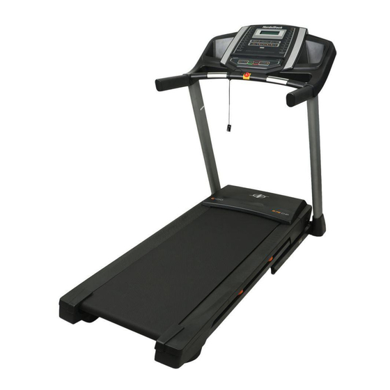
Page 5: Before You Begin
BEFORE YOU BEGIN Thank you for selecting the new NORDICTRACK ® manual. To help us assist you, note the product model C 100 treadmill. The C 100 treadmill provides an number and serial number before contacting us. The impressive selection of features designed to make your model number and the location of the serial number workouts at home more effective and enjoyable. -
Page 6: Part Identification Chart
PART IDENTIFICATION CHART Use the drawings below to identify small parts used for assembly. The number in parentheses below each draw- ing is the key number of the part, from the PART LIST near the end of this manual. The number following the key number is the quantity used for assembly. -
Page 7: Assembly
ASSEMBLY • Assembly requires two persons. • To identify small parts, see page 6. • Place all parts in a cleared area and remove the • Assembly requires the following tools: packing materials. Do not dispose of the packing the included hex keys materials until you fi... - Page 8 2. Make sure that the power cord is unplugged. Wire Press a Base Cap (74) into each side of the Base (94). Identify the Right Upright (90). Have a second person hold the Right Upright near the Base (94). See the inset drawing. Tie the wire tie in the Right Upright (90) securely around the end of the Wire Upright Wire (81).
- Page 9 4. Hold the Right Upright (90) against the Base (94). Be careful not to pinch the wires. Partially tighten three 3/8" x 4" Screws (7) with three 3/8" Star Washers (13) into the Right Upright and the Base; do not fully tighten the Screws yet.
- Page 10 6. Identify the Right Handrail (84). Attach the Right Handrail (84) to the Right Upright (90) with two 5/16" x 3" Screws (28) and two 5/16" Star Washers (11). Make sure not to pinch the Upright Wire (81). Start both Screws, and then tighten them.
- Page 11 8. IMPORTANT: To avoid damaging the Pulse Crossbar (93), do not use power tools and do not overtighten the #10 x 1 1/4" Screws (9). Orient the Pulse Crossbar (93) as shown. Attach the Pulse Crossbar to the Right and Left Handrails (84, 85) with four #10 x 1 1/4"...
- Page 12 10. Set the console assembly on the Right and Left Handrails (84, 85). Make sure that no wires Console Assembly are pinched. Insert the excess Upright Wire (81) into the Right Upright (90). Attach the console assembly to the brackets on the Handrails (84, 85) with four 1/4"...
- Page 13 12. Attach the Right and Left Trays (27, 36) with four #8 x 1/2" Screws (1). 13 Raise the Frame (56) to the upright position. Have a second person hold the Frame until step 15 is completed. Orient the Latch Crossbar (41) as shown. Make Brackets sure that the “This side toward belt”...
- Page 14 14. Orient the Storage Latch (95) so that the decals are facing away from the treadmill as shown. Attach the lower end of the Storage Latch (95) to the bracket on the Base (94) with a 5/16" x 1 3/4" Bolt (62) and a 5/16"...
- Page 15 16. Firmly tighten all six 3/8" x 4" Screws (7). Then, slide the Left and Right Base Covers (82, 83) downward. 17. Make sure that all parts are properly tightened before you use the treadmill. If there are sheets of plastic on the treadmill decals, remove the plastic.
-
Page 16: How To Use The Treadmill
HOW TO USE THE TREADMILL HOW TO PLUG IN THE POWER CORD Follow the steps below to plug in the power cord. This product must be earthed. If it should malfunc- 1. Plug the indicated end of the power cord into the tion or break down, earthing provides a path of least socket on the treadmill. - Page 17 CONSOLE DIAGRAM FEATURES OF THE CONSOLE To turn on the power, see page 18. To use the manual mode, see page 18. To use an onboard The treadmill console offers an impressive array of workout, see page 20. To use the information features designed to make your workouts more effec- mode, see page 21.
-
Page 18: To Turn On The Power
HOW TO TURN ON THE POWER HOW TO USE THE MANUAL MODE IMPORTANT: If the treadmill has been exposed to 1. Insert the key into the console. cold temperatures, allow it to warm to room tem- perature before you turn on the power. If you do See HOW TO TURN ON THE POWER at the left. - Page 19 5. Follow your progress with the displays. 6. Measure your heart rate if desired. The matrix—When Note: If you use the handgrip heart rate moni- you select the manual tor and the optional chest heart rate monitor at mode, the matrix will the same time, the console will not display your display a track that heart rate accurately.
-
Page 20: To Use An Onboard Workout
HOW TO USE AN ONBOARD WORKOUT At the end of each segment, a series of tones will sound. If a new speed and/or incline setting is 1. Insert the key into the console. programmed for the next segment, the new speed and/or incline setting will flash in the displays for a See HOW TO TURN ON THE POWER on few seconds. -
Page 21: To Adjust The Cushioning System
THE INFORMATION MODE increase and decrease buttons on the console. If you are using a personal CD player and the CD The console features an information mode that keeps skips, set the CD player on the floor or another flat track of treadmill usage information and allows you to surface instead of on the console. -
Page 22: How To Fold And Move The Treadmill
HOW TO FOLD AND MOVE THE TREADMILL HOW TO FOLD THE TREADMILL HOW TO MOVE THE TREADMILL To avoid damaging the treadmill, adjust the incline Before moving the treadmill, fold it as described at the to zero before you fold the treadmill. Then, remove left. -
Page 23: Maintenance And Troubleshooting
MAINTENANCE AND TROUBLESHOOTING MAINTENANCE SYMPTOM: The power turns off during use Regularly clean the treadmill and keep the walking a. Check the power switch (see drawing c at the left). belt clean and dry. First, press the power switch into If the switch has tripped, wait for five minutes and the off position and unplug the power cord. - Page 24 Next, locate the Reed Switch (52) and the Magnet b. If the walking belt is overtightened, treadmill per- (50) on the left side of the Pulley (49). Turn the formance may decrease and the walking belt may Pulley until the Magnet is aligned with the Reed become damaged.
- Page 25 SYMPTOM: The walking belt is not centered SYMPTOM: The walking belt slips when walked on between the foot rails a. First, remove the key and UNPLUG THE POWER IMPORTANT: If the walking belt rubs against the CORD. Using the hex key, turn both idler roller foot rails, the walking belt may become damaged.
-
Page 26: Exercise Guidelines
EXERCISE GUIDELINES Burning Fat—To burn fat effectively, you must exer- WARNING: cise at a low intensity level for a sustained period of Before beginning this time. During the first few minutes of exercise, your or any exercise program, consult your physi- body uses carbohydrate calories for energy. -
Page 27: Part List
PART LIST Model No. NETL99814.0 R0114A Key No. Qty. Description Key No. Qty. Description #8 x 1/2" Screw Reed Switch Clip #8 x 3/4" Screw Reed Switch Base Pad 1/4" x 1 1/2" Screw 1/4" x 1/2" Screw Drive Motor #10 Star Washer Motor Belt 5/16"... -
Page 28: Exploded Drawing
EXPLODED DRAWING A Model No. NETL99814.0 R0114A... - Page 29 EXPLODED DRAWING B Model No. NETL99814.0 R0114A...
- Page 30 EXPLODED DRAWING C Model No. NETL99814.0 R0114A...
- Page 31 EXPLODED DRAWING D Model No. NETL99814.0 R0114A...
-
Page 32: Ordering Replacement Parts
ORDERING REPLACEMENT PARTS To order replacement parts, please see the front cover of this manual. To help us assist you, be prepared to provide the following information when contacting us: • the model number and serial number of the product (see the front cover of this manual) •...
Need help?
Do you have a question about the C100 and is the answer not in the manual?
Questions and answers
Good morning, hopefully you will be able to help, when I'm running on the treadmill it keeps slowing down and then it will get faster and then it also will stop suddenly when I'm running which is quite dangerous, I know my machine is over 10years old could it be this ? Many thanks Tracy .
The NordicTrack C100 treadmill could slow down, speed up, or stop suddenly due to the following reasons:
1. Emergency Key Removal – If the key is pulled from the console, the walking belt will slow to a stop.
2. Speed Button Pressed – Pressing a numbered Speed button will cause the treadmill to change speed gradually.
3. Stop Button Pressed – Pressing the Stop button will stop the walking belt.
4. Incline Adjustment – Pressing the Incline increase or decrease button may cause speed variations as the treadmill adjusts.
5. Power Switch Issue – If the power switch trips, the treadmill may turn off during use.
Regular maintenance, including cleaning the walking belt and ensuring all parts are properly tightened, can help prevent sudden changes in performance.
This answer is automatically generated