
Subscribe to Our Youtube Channel
Related Manuals for Technifor XF510Cr

Summary of Contents for Technifor XF510Cr
- Page 1 OPERATING AND MAINTENANCE MANUAL XF510Cr/Sr/Dr INTEGRABLE MARKING HEAD NUMERICALLY CONTROLLED MARKING BY SCRIBING Technifor reserves all rights to modify its products. www.technifor.com This document is non contractual.
-
Page 2: Table Of Contents
Mounting ............................15 Effort exerted on the mounting plate ....................16 Efforts exerted on the part ....................... 20 Possible integration and operating positions for the XF510Cr/Sr/Dr ..........21 2. Coordinate system ..........................22 3. Compressed air supply ......................... 22 4. Connection of the marking head to the CCU ..................23 5. -
Page 3: A - Introduction
• 1 identification plate on the marking head • 1 identification plate on the Control Unit Have the model and serial number of the equipment available when contacting Technifor. 3. Power • power supply: 115 V AC - 230 V AC - 50/60 Hz •... -
Page 4: Declaration Of Incorporation
EU directives. These modifications void Technifor’s liability. In this case, the machine and equipment installer is responsible for the final work station’s compliance. -
Page 5: Work Station Safety
Instructions for use and warranty limitations This equipment is designed to mark material using Technifor scribing styli only. Any other use, or the use of styli other than those provided by Technifor is not recommended. Technifor will not be held responsible for the results. - Page 6 • Turn off the machine before beginning any cleaning, maintenance or repair procedure. Technifor will not be held responsible for injuries resulting from disregard for the above operating instructions or other general safety rules applicable to the use of this equipment. Furthermore, disregard for the instructions will void the warranty.
-
Page 7: B - Operating Instructions For The Machine
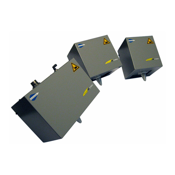
Operating instructions for the machine 1. Description of the machine The XF510Cr/Sr/Dr is a numerically controlled scribing marking machine. Integrated in a special machine or on a production line, this compact head is the ideal solution for marking parts of various shapes and sizes, whether flat or curved. -
Page 8: Technical Specifications
10 kg (22.046 lb) 11.5 kg (25.353 lb) Marking area 40 mm (1.575 in) 80 mm (3.15 in) 160 mm (6.299 in) x 50 mm (1.969 in) x 50 mm (1.969 in) x 50 mm (1.969 in) Ref. DCD01/3074 - XF510Cr-Sr-Dr_en_C 8/31... -
Page 9: Dimensional Drawings
4 : Head attachment: 4 M6 (max. depth 8 mm (0.315 in)) 5 : Pneumatic connection for Ø4x6 tube 6 : Electrical connector 7 : Marking area: 40 mm (1.575 in) x 50 mm (1.969 in) Ref. DCD01/3074 - XF510Cr-Sr-Dr_en_C 9/31... -
Page 10: Xf510Sr
4 : Head attachment: 4 M6 (max. depth 8 mm (0.315 in)) 5 : Pneumatic connection for Ø4x6 tube 6 : Electrical connector 7 : Marking area: 80 mm (3.15 in) x 50 mm (1.969 in) Ref. DCD01/3074 - XF510Cr-Sr-Dr_en_C 10/31... -
Page 11: Xf510Dr
4 : Head attachment: 4 M6 (max. depth 8 mm (0.315 in)) 5 : Pneumatic connection for Ø4x6 tube 6 : Electrical connector 7 : Marking area: 160 mm (6.299 in) x 50 mm (1.969 in) Ref. DCD01/3074 - XF510Cr-Sr-Dr_en_C 11/31... -
Page 12: List Of Accessories Available Upon Request
1 mm (0.039 in), and in certain conditions, from spattering of liquid (N/A for stylus pointing up). XF510Sr: Ref.: 52876 XF510Dr: Ref.: 52881 DataMatrix kit Ref.: 52877 • Used to manage different pressures between scribing and marking of a DataMatrix code. Ref. DCD01/3074 - XF510Cr-Sr-Dr_en_C 12/31... - Page 13 The foot pedal is not designed to stop marking. Ref.: 52713 • Industrial footswitch: Same use as described above. This foot pedal is especially designed for industrial work environments or for high rate production. Ref. DCD01/3074 - XF510Cr-Sr-Dr_en_C 13/31...
- Page 14 Ref.: 52853 3 m (9.842 ft) Head/CCU connecting cable Ref.: 52854 6 m (19.685 ft) Head/CCU connecting cable Ref.: 52855 10 m (32.808 ft) Head/CCU connecting cable Ref.: 52856 15 m (49.212 ft) Head/CCU connecting cable Ref. DCD01/3074 - XF510Cr-Sr-Dr_en_C 14/31...
-
Page 15: C - Installation
Torque is 8.3 Nm (6.119 lb ft) maximum (class 8.8 screw). Only the back side of the XF510Cr/Sr/Dr integrable head should be attached for mounting. To obtain a uniform mark over the whole marking surface, mount the head so that it is parallel to the surface to be marked. -
Page 16: Effort Exerted On The Mounting Plate
36.9 Cy max (daN.m) Cy min (daN.m) -1.2 -2.8 -3.7 -5.0 -5.6 Cx max (daN.m) Cx min (daN.m) -0.7 -1.6 -2.4 -2.4 -3.0 Cz (daN.m) ± 0.9 ± 2.1 ± 2.1 ± 4.1 ± 4.1 Ref. DCD01/3074 - XF510Cr-Sr-Dr_en_C 16/31... - Page 17 Approximative forces and couplings exerted on the head’s fastening, brought to point A, without taking into account the forces and couplings due to the machine’s weight, depending on the integration’s position (for this calculation: consider the center of gravity as being at the center of the machine’s volume) Ref. DCD01/3074 - XF510Cr-Sr-Dr_en_C 17/31...
- Page 18 ± 5.2 Approximative forces exerted on the part to mark Stylus NA1 LG 100 Fx = Fy (daN) ± 8.0 ± 18.8 ± 18.8 ± 36.9 ± 36.9 Fz (daN) -8.0 -18.8 -18.8 -36.9 -36.9 Ref. DCD01/3074 - XF510Cr-Sr-Dr_en_C 18/31...
- Page 19 36.9 Cy max (daN.m) Cy min (daN.m) -0.6 -1.5 -2.4 -2.4 -3.0 Cx max (daN.m) Cx min (daN.m) -0.7 -1.6 -2.4 -2.4 -3.0 Cz (daN.m) ± 1.4 ± 3.4 ± 3.4 ± 6.7 ± 6.7 Ref. DCD01/3074 - XF510Cr-Sr-Dr_en_C 19/31...
-
Page 20: Efforts Exerted On The Part
For typical steels, lateral effort in X-Y is equal to the axial effort. These values are used to dimension the clamping of the part in relation with the desired safety coefficient. Poor clamping may allow the part to move and the stylus point to break. Ref. DCD01/3074 - XF510Cr-Sr-Dr_en_C 20/31... -
Page 21: Possible Integration And Operating Positions For The Xf510Cr/Sr/Dr
Installation Possible integration and operating positions for the XF510Cr/Sr/Dr Stylus vertical pointing down Stylus vertical pointing up Position impossible Risk of particles penetrating inside the head. Choose a version with protective boot. Horizontal stylus Horizontal stylus Position 2 Position 1... -
Page 22: Coordinate System
Coordinate system 1 : XF510Cr: marking area: 40 mm (1.575 in) x 50 mm (1.969 in) 2 : XF510Sr: marking area: 80 mm (3.15 in) x 50 mm (1.969 in) 3 : XF510Dr: Marking area: 160 mm (6.299 in) x 50 mm (1.969 in) 3. -
Page 23: Connection Of The Marking Head To The Ccu
If a stylus is set too high, it doesn’t mark because the point doesn’t touch the plate consistently while tracing the characters. 6. Definition of operating distances of a stylus See styli manual. 7. Using the T05 program Refer to the user manual for the T05 program. Ref. DCD01/3074 - XF510Cr-Sr-Dr_en_C 23/31... -
Page 24: D - Preventive Maintenance
1. Every week • Empty the air filter in order to eliminate dust or liquid which XF510Cr/Sr/Dr - Top view may be present in the system. Clean, dry, non-lubricated air will reduce the build-up of grease in the solenoid valves. -
Page 25: Every Year
• 8 continuous working hours on steel strength 50 DaN/mm (72518.869 lb/in During servicing of the marking head, Technifor can provide identical rental equipment so that production is not interrupted. Contact your distributor to schedule an appointment for servicing. This "tune-up" does not take a long time. -
Page 26: E - Wearing And Spare Parts
Carbide scribing stylus NA22 110° with radius 0.2 mm (0.008 in) Repair kits: Reference Description Ref.: 57989 Repair kit (o-ring /spring) for NA0 stylus Ref.: 57482 Repair kit (o-ring /spring) for NA1 stylus Ref.: 55876 Repair kit (o-ring /spring) for N2-NA22 stylus Ref. DCD01/3074 - XF510Cr-Sr-Dr_en_C 26/31... -
Page 27: Spare Parts
RNA22 carbide point 110° LG 52 mm (2.047 in) R=0.2 mm (0.008 in) for scribing stylus NA22 2. Spare parts XF510Cr/Sr/Dr Reference Description Ref.: 54899 Detector unit (X Or Y) Ref.: 54898 Quick solenoid valve Ref.: 64994 Air filter Ref. DCD01/3074 - XF510Cr-Sr-Dr_en_C 27/31... -
Page 28: Xf510Sr
Ref.: 52876 Mobile protective shutters Ref.: 66767 Head casing with decals Ref.: 52242 Internal wiring harness XF510Dr Reference Description Ref.: 52881 Mobile protective shutters Ref.: 66780 Head casing with decals Ref.: 52241 Internal wiring harness Ref. DCD01/3074 - XF510Cr-Sr-Dr_en_C 28/31... -
Page 29: F - Noise Emission Of The Machine
• Marking speed: 100% • Movement speed: 100% • Compressed air system pressure: 3 Bar (43.511 PSI) • Marking quality: 100% • Stroke force: 100% • Marking of 1 line(s) of 10 character(s) 5 mm (0.197 in) high Ref. DCD01/3074 - XF510Cr-Sr-Dr_en_C 29/31... -
Page 30: Noise Emission Information
74 dB(A) 85.5 dB(C) 71 dB(A) 80 dB(C) When marking resonant parts (metallic, hollow, thin), wear hearing protection for sound levels L > 85 dB(A) or L > 137 dB(C). Similar results for XF510Cr/Dr machines. Ref. DCD01/3074 - XF510Cr-Sr-Dr_en_C 30/31... -
Page 31: G - Appendix
Tel.: (55) 11 5541 74 93 Fax: (61) 29 684 2500 C.P. 11598 MEXICO Fax: (55) 11 5541 74 93 E-mail: sales@gravograph.com.au Tel.: (52) 55 5357-2766 / 67 E-mail: vendas@ltda.technifor.com Fax: (52) 55 5357-2765 E-mail: nparizon@gravograph-newhermes.com Ref. DCD01/3074 - XF510Cr-Sr-Dr_en_C 31/31...
Need help?
Do you have a question about the XF510Cr and is the answer not in the manual?
Questions and answers