Table of Contents
Advertisement
Quick Links
Service Manual
The picture in this service manual is only for reference, and specific appearance
and configuration are subject to the real product.
This manual mainly teaches the method, the specific work skill needs engineer to
accumulate through the daily work.
There are special components used in this equipment which are important for safety. These parts are marked
by
in the Schematic Diagrams, Circuit Board Diagrams, Exploded Views and Replacement Parts List. It is
essential that these critical parts should be replaced with manufacturer's specified parts to prevent shock, fire
or other hazards. Do not modify the original design without permission of manufacturer.
CHEST FREEZER SERIES
Applicable Models
HS-185CN
Important Safety Notice
Model Code
Applicable Models
UR-BD143C1-DQ
WARNING
1
Service Manual_2018-V2.0
22032010003422
Advertisement
Table of Contents

Related Manuals for Midea HS-185CN


Summary of Contents for Midea HS-185CN
- Page 1 Service Manual CHEST FREEZER SERIES Applicable Models Model Code Applicable Models HS-185CN UR-BD143C1-DQ 22032010003422 The picture in this service manual is only for reference, and specific appearance and configuration are subject to the real product. This manual mainly teaches the method, the specific work skill needs engineer to accumulate through the daily work.
- Page 2 Manufacturers or distributors are not responsible for the content of the Manual and interpretation thereof. Midea Refrigerators Technical Maintenance Manual Copyright @2017 All rights reserved. Replication of all or part of the Manual in any forms shall not be allowed without written approval by the Overseas Sales Corporation of Midea Refrigerators.
-
Page 3: Table Of Contents
Service Manual_2018-V2.0 Contents SIGNIFICANT UPDATE NOTES(NONE) ......................5 2. SAFETY WARNING CODE ............................6 2.1 W ........................... 6 ARNING FOR OPERATION SAFETY ......................... 8 2.2 S AFETY INSTRUCTION FOR REFRIGERANT 3. TRANSPORT ................................9 3.1 H ................................... 9 ANDLING 4. INSTALLATION AND COMMISSIONING ......................10 4.1D ) ...................... - Page 4 Service Manual_2018-V2.0 ..................29 10.1C OMPRESSOR ON AND OFF ONTROL SPECIFICATIONS 11. TROUBLESHOOTING METHOD ........................30 ................................30 11.1N OT COOLING 11.2 N ..........................31 O WORKING OF COMPRESSOR ....................... 31 11.3T HERMOSTAT MALFUNCTION NDERCOOLING ..............................32 11.4 L IGHT IS NOT ON 11.5 N ..................................
-
Page 5: Significant Update Notes(None)
Service Manual_2018-V2.0 1. Significant update notes(None) -
Page 6: Safety Warning Code
Service Manual_2018-V2.0 2. Safety Warning Code 2.1 Warning for operation safety Important Safety Instructions CAUTION RISK OF ELECTRIC SHOCK DO NOT OPEN This symbol indicates that dangerous voltage constituting a risk of electric shock is present within your freezer. This symbol indicates that there are important operating and maintenance instructions in the literature accompanying your freezer. - Page 7 Service Manual_2018-V2.0 CONNECTING ELECTRICITY Electrical Shock Hazard. Failure to follow these instructions can Plug into a grounded 3-prong outlet. result in death, fire, or electrical shock. Do not remove the ground prong. Do not use an adapter. WARNING Electric Shock Hazard Failure to follow these instructions can result in electric shock, fire, or death.
-
Page 8: Safety Instruction For Refrigerant
Service Manual_2018-V2.0 13) Do not store or use gasoline or any flammable liquids inside or in the vicinity of this freezer. 14) Do not use extension cords or ungrounded (two-prong) adapters with this freezer. If the power cord is too short, have a qualified electrician install an outlet near the freezer. Use of an extension cord can negatively affect the freezer’s performance. -
Page 9: Transport
Service Manual_2018-V2.0 3. Transport 3.1 Handling Handling 1)Protect the refrigerator in moving it,Same as shown as lef t photo, please move it by handcart with cushion 2)Remove all packing materials and bottom cushion, the m ove into house for placement 3)After moving it to appropriate location, wait for 2 hours bef ore power on. -
Page 10: Installation And Commissioning
Service Manual_2018-V2.0 4. Installation and commissioning 4.1Door Disassembly and Assembly(None) The refrigerator door needs to be dismantled if it cannot enter the room in the whole. 4.2 Installation location Installation location Location that is easy for ventilation shall be chosen to facilitate heat dissipation, enhance its performance and reduce the energy consumption. -
Page 11: Installation Of Door Lock(None
Service Manual_2018-V2.0 1- Handle 2- M5*14 screw(two) 3- Screw hole cover (two) 1) The handle is inserted below the display control board of door, aligning with the screw hole. 2) Fixing the handle by using the screw. 3) Assemble the screw hole cover onto the screw hole. 1.Fix the lock loop to its mounting hole near the frame in the front side plate of the box with a M4x20 or M4x8 screw. -
Page 12: Product Configuration And Dimension
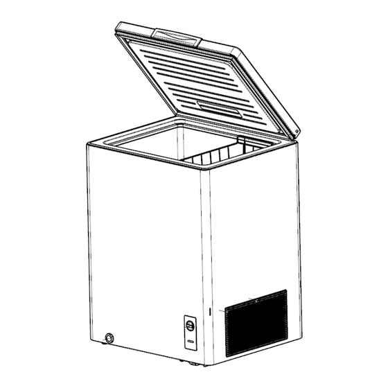
Service Manual_2018-V2.0 5. Product configuration and dimension 5.1 Main parts and their names (The picture is only for reference, and specific appearance and configuration are subject to the real product) Freezer chamber Refrigerator chamber ❶ Door shell ❼ Compressor mounting panel ❷... -
Page 13: External Dimension
Service Manual_2018-V2.0 5.2 External dimension HS-185CN HS-259CN Description Code Size (mm) Size (mm) Height to Top of Case Width Depth/Hinge Depth Height (Door open) 1350 1350 (The picture is only for reference) -
Page 14: Location Of S/N
Service Manual_2018-V2.0 5.3 Location of S/N Some products also have S/N on the lower part of the right side of the Cabinet. -
Page 15: Product Specification
Service Manual_2018-V2.0 6. Product specification 6.1 Electrical parameters Applicable Models HS-185CN Product Name UR-BD143C1-DQ Product Code 22032010003422 Item Specification Specification Refrigerant R600a Compressor FZ59E1G Starter(PTC) QP2-4R7 Overload protector(OLP) DRB29T61A1 Integrate PTC+OLP None Variable frequency driver board None Capacitor None Rmc:27±7%Ω... -
Page 16: Circuit Diagram
Service Manual_2018-V2.0 6.3 Circuit diagram... -
Page 17: Refrigerating Piping System And Circulating Route Of Cooling Air
Service Manual_2018-V2.0 7.Refrigerating piping system and circulating route of cooling air 7.1 Refrigerating piping system ❶Compressor→❷Right condenser→❸Left Condenser→❹Dry filter→❺Capillary tube→❻Evaporator 7.2 Special soldering position... -
Page 18: Dismantling Of Parts
Service Manual_2018-V2.0 8. Dismantling of parts 8.1 Parts on the door Door seal 1)Pull the door seal from the corner 2)Take efforts until door seal totally detaches from door inner liner groove, remove the door seal 3)Fixing the four corners and pressing smoothly. The hinge cover The hinge cover teardown 1)Push the hinge cover from the bottom to the top and... - Page 19 Service Manual_2018-V2.0 Open the 2)slanted upward of hinge cover to a certain angle by a screwdriver and remove the hinge cover. Wear safety gloves for fear of cutting the hand. The hinge cover install 1)When the door is closed, open the lower hinge cover along the side wall to a suitable angle and push forwards into the side wall of the hinge until the hinge cover boss completely falls into the hinge hole.
-
Page 20: Parts Inside The Refrigerator
Service Manual_2018-V2.0 8.2Parts inside the refrigerator Basket Open the door and upwardly lift the basket Note: There are plastic baskets and wire baskets, and the basket we offer you is subject to the real product you received. Inside water pipe cover Counterclockwise to remove the pipe cover 8.3 Light system Door light disassembly and assembly... -
Page 21: Compressor Case
Service Manual_2018-V2.0 8.4 Compressor case shutter Pull down the screw, open the shutter. Compressor and the cooling system pipe 1)Cut off the compressor pipeline.-❶Cut off the process pipeline.-❷Cut off the low-pressure muffler.-❸Cut off the high-pressure exhaust pipe. 2-1)Remove the screws(for some models) -Two screws outside -One screw inside 2-2)Remove the metal clamp(for some models) - Page 22 Service Manual_2018-V2.0 4)Remove the protective cover -Pry the protective cover slowly from the upper part, -Pull it out and remove it. 5)Remove the starter and protector Unplug the starter and protector (you can use a screwdriver to pry it slowly) 6)Loosen the screw of the compressor bottom plate, remove the floor together with the compressor from the box.
- Page 23 Service Manual_2018-V2.0 8)Use Pipe cutter cut off the condenser tube❽, then Shear off capillary ❾ by the capillary tube scissors. 9)Replace the compressorand welding the compressor pipeline.-❿Welding the process pipeline.-⓫Welding the low-pressure muffler.-⓬Welding the high-pressure exhaust pipe. 10)Replace the filter, Cu-Fe tubes welding ⓭ used Ag welding rod, Cu-Cu tubes welding ⓮...
-
Page 24: T Emperature - Control Box Assembly
Service Manual_2018-V2.0 13)Use the vise grip pliers clamp the middle of the process pipe, then seal welding process tube⓯⓰. Piping system in the compressor case ❶ Capacitor ❿ Compressor ❷ -1 Front condenser pipeline-1 ⓫ Suction Pipe ❸ -2 Rear condenser pipeline-2 ⓬... - Page 25 Service Manual_2018-V2.0 Destuffing 1)Take out of temperature control box assembly by pressing shrapnel with the hands. Note:there are four shrapnels separately in the four corners,require enough strength to press shrapnel. Suggest pressing one and pushing toward the corner, as the above one by one. 2)Take out of temperature control box assembly after four corner pushed out.
- Page 26 Service Manual_2018-V2.0 4)Pull out the wiring harness and indicator light 5)Pull out the control knob 6)Pull out the fixed nut of the thermostat 7) remove the indicator light and thermostat, the reverse operation is for assembly...
-
Page 27: Function And Operation
Service Manual_2018-V2.0 9. Function and operation 9.1 Operation panel Icons Button ❶ Indicator hole cover/Power indicator ACooling gear B “OFF” C Freezer gear 9.2Temperature control Control panel without indicator light 1. Connect the freezer to power supply; 2. The temperature in the box is adjusted by the temperature control knob, the temperature in the box is reduced by the clockwise rotation of the temperature control knob, in the range of "COOLING", the temperature in the box is refrigerated, in the range of "FREEZING", the temperature in the box is frozen;... -
Page 28: High Temperature An Alarm(None)
Service Manual_2018-V2.0 9.3High temperature an alarm(None) 9.4Defrosting function Unplug the freezer and open the freezer door, remove foods and drawers before defrosting; Open the outflow holes and drainage holes(and place water container at the outflow holes); indoor frost will naturally melt, wipe the defrost water with a dry, soft cloth. When the frost softens, an ice scraper might be used to the accelerate de-icing process. -
Page 29: Compressor
Service Manual_2018-V2.0 10. Compressor 10.1Compressor on and off Control specifications 1.1 When one of the following conditions is met, the compressor stops: 1) Tr ≤ Trt; 2) The compressor runs continuously for more than 3 hours (Stop 5 minutes); 1.2 When all the following conditions are met, the compressor starts up: 1) Tr ≥Trk;... -
Page 30: Troubleshooting Method
Service Manual_2018-V2.0 11. Troubleshooting Method 11.1Not cooling... -
Page 31: No Working Of Compressor
Service Manual_2018-V2.0 11.2 No working of compressor 11.3Thermostat malfunction-Undercooling... -
Page 32: Light Is Not On
Service Manual_2018-V2.0 11.4 Light is not on 11.5 Noise... -
Page 33: Figures And Details Of Repair Parts
Service Manual_2018-V2.0 13. Figures and details of repair parts See this section in the TSP. - Page 34 MIDEA appliances after sales website tsp.midea.com For more information about Midea appliances after sales, please visit the tsp.midea.com For more information about the service manual, please visit the tsp.midea.com For more information about the EV and SBOM, please visit the...
Need help?
Do you have a question about the HS-185CN and is the answer not in the manual?
Questions and answers