Table of Contents
Advertisement
Quick Links
Service Manual
The picture in this service manual is only for reference, and specific appearance
and configuration are subject to the real product.
This manual mainly teaches the method, the specific work skill needs engineer to
accumulate through the daily work.
CHEST FREEZER SERIES
Applicable Models
HS-131CN
HS-131CN
Model Code
Applicable Models
UR-BD100-DQ 22032010003261
UR-BD100-DQ 92032010Z00401
1
Service Manual_2018-V2.0
Advertisement
Table of Contents

Related Manuals for Midea HS-131CN


Summary of Contents for Midea HS-131CN
- Page 1 Service Manual_2018-V2.0 Service Manual CHEST FREEZER SERIES Applicable Models Model Code Applicable Models HS-131CN UR-BD100-DQ 22032010003261 HS-131CN UR-BD100-DQ 92032010Z00401 The picture in this service manual is only for reference, and specific appearance and configuration are subject to the real product.
- Page 2 Manufacturers or distributors are not responsible for the content of the Manual and interpretation thereof. Midea Refrigerators Technical Maintenance Manual Copyright @2017 All rights reserved. Replication of all or part of the Manual in any forms shall not be allowed without written approval by the Overseas Sales Corporation of Midea Refrigerators.
-
Page 3: Table Of Contents
Service Manual_2018-V2.0 Contents 重要更新说明 SIGNIFICANT UPDATE NOTES(NONE)................5 2. 安全警示规范 SAFETY WARNING CODE ......................6 2.1 作业安全警告 W ..................6 ARNING FOR OPERATION SAFETY 2.2 冷媒安全须知 S ................8 AFETY INSTRUCTION FOR REFRIGERANT 3. 运输 TRANSPORT ............................9 3.1 搬运 H ............................9 ANDLING 4. 安装和调试 INSTALLATION AND COMMISSIONING ................. 10 4.1 门体拆装... - Page 4 Service Manual_2018-V2.0 10. 压缩机 COMPRESSOR ..........................29 10.1 压缩机的开停控制规则 C .......... 29 OMPRESSOR ON AND OFF ONTROL SPECIFICATIONS 11. 故障排除方法 TROUBLESHOOTING METHOD ..................30 11.1 不制冷 N ..........................30 OT COOLING 11.2 压缩机不工作 N ..................31 O WORKING OF COMPRESSOR 11.3 温控器故障-过冷...
-
Page 5: 重要更新说明 Significant Update Notes(None)
Service Manual_2018-V2.0 1. Significant update notes(None) -
Page 6: 安全警示规范 Safety Warning Code
Service Manual_2018-V2.0 2. Safety Warning Code 2.1 Warning for operation safety Important Safety Instructions CAUTION RISK OF ELECTRIC SHOCK DO NOT OPEN This symbol indicates that dangerous voltage constituting a risk of electric shock is present within your freezer. This symbol indicates that there are important operating and maintenance instructions in the literature accompanying your freezer. - Page 7 Service Manual_2018-V2.0 CONNECTING ELECTRICITY Electrical Shock Hazard. Failure to follow these instructions can Plug into a grounded 3-prong outlet. result in death, fire, or electrical shock. Do not remove the ground prong. Do not use an adapter. WARNING Electric Shock Hazard Failure to follow these instructions can result in electric shock, fire, or death.
-
Page 8: 冷媒安全须知 Safety Instruction For Refrigerant
Service Manual_2018-V2.0 13) Do not store or use gasoline or any flammable liquids inside or in the vicinity of this freezer. 14) Do not use extension cords or ungrounded (two-prong) adapters with this freezer. If the power cord is too short, have a qualified electrician install an outlet near the freezer. Use of an extension cord can negatively affect the freezer’s performance. -
Page 9: 运输 Transport
Service Manual_2018-V2.0 3. Transport 3.1 Handling Handling 1)Protect the refrigerator in moving it,Same as shown as lef t photo, please move it by handcart with cushion 2)Remove all packing materials and bottom cushion, the m ove into house for placement 3)After moving it to appropriate location, wait for 2 hours bef ore power on. -
Page 10: 安装和调试 Installation And Commissioning
Service Manual_2018-V2.0 4. Installation and commissioning 4.1Door Disassembly and Assembly(None) The refrigerator door needs to be dismantled if it cannot enter the room in the whole. 4.2 Installation location Installation location Location that is easy for ventilation shall be chosen to facilitate heat dissipation, enhance its performance and reduce the energy consumption. -
Page 11: 门锁安装 Installation Of Door Lock (None
Service Manual_2018-V2.0 1- Handle 2- M5*14 screw(two) 3- Screw hole cover (two) 1) The handle is inserted below the display control board of door, aligning with the screw hole. 2) Fixing the handle by using the screw. 3) Assemble the screw hole cover onto the screw hole. 1.Fix the lock loop to its mounting hole near the frame in the front side plate of the box with a M4x20 or M4x8 screw. -
Page 12: 产品配置和尺寸 Product Configuration And Dimension
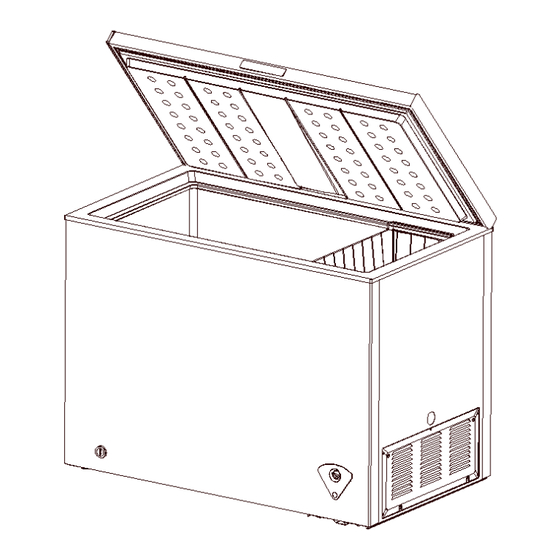
Service Manual_2018-V2.0 5. Product configuration and dimension 5.1 Main parts and their names (The picture is only for reference, and specific appearance and configuration are subject to the real product) Freezer chamber Refrigerator chamber ❶ Door shell ❼ Levelling feet ❷... -
Page 13: Xternal Dimension
Service Manual_2018-V2.0 5.2 External dimension HS-131CN Description Code Size (mm) Height to Top of Case Width Depth/Hinge Depth Height (Door open) 1265 (The picture is only for reference) -
Page 14: Ocation Of S/N
Service Manual_2018-V2.0 5.3 Location of S/N Some products also have S/N on the lower part of the right side of the Cabinet. -
Page 15: 产品规格 Product Specification
Service Manual_2018-V2.0 6. Product specification 6.1 Electrical parameters Applicable Models HS-131CN Product Name UR-BD100-DQ Product Code 22032010003261 Item Specification Specification Refrigerant R600a Compressor FZ35C1M Starter(PTC) QPS-4R7 Overload protector(OLP) DRB18T61A1 Integrate PTC+OLP None Variable frequency driver board None Capacitor None Rmc:12.74-14.66Ω... -
Page 16: Ircuit Diagram
Service Manual_2018-V2.0 6.3 Circuit diagram... -
Page 17: Cooling Air
Service Manual_2018-V2.0 7.Refrigerating piping system and circulating route of cooling air 7.1 Refrigerating piping system ❶Compressor→❷Right condenser→❸Left Condenser→❹Dry filter→❺Capillary tube→❻Evaporator 7.2 Special soldering position(None) -
Page 18: 部件拆装 Dismantling Of Parts
Service Manual_2018-V2.0 8. Dismantling of parts 8.1 Parts on the door Door seal 1)Pull the door seal from the corner 2)Take efforts until door seal totally detaches from door inner liner groove, remove the door seal 3)Fixing the four corners and pressing smoothly. The hinge cover The hinge cover teardown 1) Strongly apart a proper angle with your hands along... -
Page 19: Arts Inside The Refrigerator
Service Manual_2018-V2.0 The hinge cover install 1) Apart a proper angle with your hands along the side wall of the lower hinge cover when the refrigerator door is closed, align to the side wall of hinge and push forward until the hinge cover boss is fully and correctly inserted into the hinge holes;... -
Page 20: Ight System
Service Manual_2018-V2.0 8.3 Light system Door lamp Door lamp disassembly 1) Open the refrigerator door to dismantle the lamp cover; Note: There are two kinds of door lamps, namely, incandescent lamp and LED lamp, and what is shown in the picture is the incandescent lamp. 2) Screw off the screws to remove the incandescent lamp holder or LED lamp panel;... - Page 21 Service Manual_2018-V2.0 1)Cut off the compressor pipeline.-❶Cut off the process pipeline.-❷Cut off the low-pressure muffler.-❸Cut off the high-pressure exhaust pipe. 2-1)Remove the screws(for some models) -Two screws outside -One screw inside 2-2)Remove the metal clamp(for some models) -Disassembly the metal clamp that is fix the electric appliance shield 3)Remove the clipping strip Slowly pull it out...
- Page 22 Service Manual_2018-V2.0 5)Remove the starter and protector Unplug the starter and protector (you can use a screwdriver to pry it slowly) 6)Loosen the screw of the compressor bottom plate, remove the floor together with the compressor from the box. 7)Use the wrench to remove the bolts by steps❹❺❻❼, replace the compressor and reverse process can complete installation.
- Page 23 Service Manual_2018-V2.0 9)Replace the compressorand welding the compressor pipeline.-❿Welding the process pipeline.-⓫Welding the low-pressure muffler.-⓬Welding the high-pressure exhaust pipe. 10)Replace the filter, Cu-Fe tubes welding ⓭ used Ag welding rod, Cu-Cu tubes welding ⓮ used Cu welding rod. 11)Vacuum system,The degree of vacuum below 6Pa. 12)Perfusion refrigerant.
-
Page 24: 温控盒组件 Temperature - Control Box Assembly
Service Manual_2018-V2.0 ❷ -1 Front condenser pipeline-1 ⓫ Suction Pipe ❸ -2 Rear condenser pipeline-2 ⓬ -1 Rear condenser pipeline-1 ❹ -1Anti-dew pipe-1 ⓭ -2 Front condenser pipeline-2 ❺ Temperature-control box assembly ⓮ -2Anti-dew pipe-2 ❻ Drying filter ⓯ Compressor Assembly Board ❼... - Page 25 Service Manual_2018-V2.0 Destuffing 1)Pull down the screw, open the shutter. 2) Pull out the temperature probe from the temperature tube 3)Hold two tabs on the back cover of temperature-control box to remove the components 4)Use screwdriver to remove the two screws...
- Page 26 Service Manual_2018-V2.0 5)Separate the temperature-control box from the panel 6)Pull out the control knob 7)Pull out the fixed nut of the thermostat 8) Pull out the wiring harness and indicator light。remove the indicator light and thermostat, the reverse operation is for assembly...
-
Page 27: 功能和操作 Function And Operation
Service Manual_2018-V2.0 9. Function and operation 9.1 Operation panel Icons Button ❶ Indicator hole cover/Power indicator Ⓐ freezer gear Ⓑ “OFF” 9.2Temperature control ◆ Control panel without indicator light 1. Connect the freezer to power supply; 2. The interior temperature of the freezer is adjusted through the thermostat knob. Clock wisely rotate the thermostat knob and the interior temperature will drop.“MIN”is the warmest setting, “MAX”is the coldest setting. -
Page 28: 高温报警 High Temperature An Alarm
Service Manual_2018-V2.0 9.3High temperature an alarm(None) 9.4Defrosting function Unplug the freezer and open the freezer door, remove foods and drawers before defrosting; Open the outflow holes and drainage holes(and place water container at the outflow holes); indoor frost will naturally melt, wipe the defrost water with a dry, soft cloth. When the frost softens, an ice scraper might be used to the accelerate de-icing process. -
Page 29: 压缩机 Compressor
Service Manual_2018-V2.0 10. Compressor 10.1Compressor on and off Control specifications 1.1 When one of the following conditions is met, the compressor stops: 1) Tr ≤ Trt; 2) The compressor runs continuously for more than 3 hours (Stop 5 minutes); 1.2 When all the following conditions are met, the compressor starts up: 1) Tr ≥Trk;... -
Page 30: 故障排除方法 Troubleshooting Method
Service Manual_2018-V2.0 11. Troubleshooting Method 11.1Not cooling... -
Page 31: O Working Of Compressor
Service Manual_2018-V2.0 11.2 No working of compressor 11.3Thermostat malfunction-Undercooling... -
Page 32: Ight Is Not On
Service Manual_2018-V2.0 11.4 Light is not on 11.5 Noise... -
Page 33: 维修零部件图示和明细 Figures And Details Of Repair Parts
Service Manual_2018-V2.0 13. Figures and details of repair parts See this section in the TSP. - Page 34 MIDEA appliances after sales website tsp.midea.com For more information about Midea appliances after sales, please visit the tsp.midea.com For more information about the service manual, please visit the tsp.midea.com For more information about the EV and SBOM, please visit the...
Need help?
Do you have a question about the HS-131CN and is the answer not in the manual?
Questions and answers