Sign In
Upload
Download
Table of Contents
Contents
Add to my manuals
Delete from my manuals
Share
URL of this page:
HTML Link:
Bookmark this page
Add
Manual will be automatically added to "My Manuals"
Print this page
×
Bookmark added
×
Added to my manuals
Manuals
Brands
AFINIA LABEL Manuals
Label Maker
Mini DLF Series
User manual
AFINIA LABEL Mini DLF Series User Manual
Tabletop label finishing system
Hide thumbs
1
2
3
4
5
6
7
8
9
10
11
12
13
14
15
16
17
18
19
20
21
22
23
24
25
26
27
28
29
30
31
32
33
34
35
36
37
38
39
40
41
42
43
44
45
46
47
page
of
47
Go
/
47
Contents
Table of Contents
Bookmarks
Table of Contents
How to Install the Cutting Plotter
Software Activation
System Requirements
How to Load the Matrix Remover Core Holder
Cutting Direction
Advanced Options
How to Update Software
Device Selector
Communication Specifications
Correct Position
Black-Mark Position in the Media
How to Restore Plotter Settings
Media Path
How to Replace the Slitter Blade
How to Replace the Cutting Mat
Advertisement
Quick Links
Download this manual
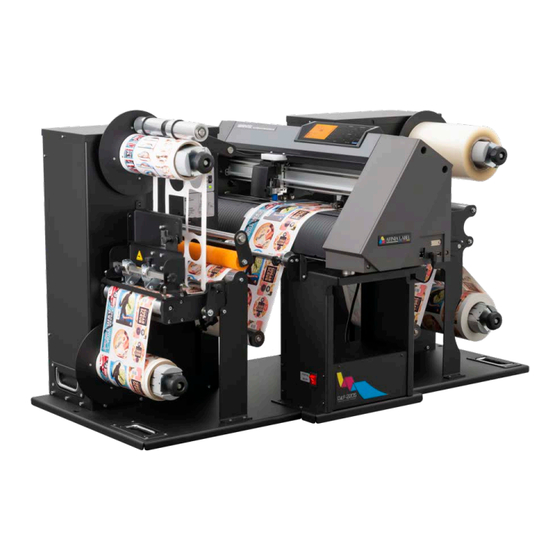
Mini DLF Series
USER MANUAL
DLF-140S / DLF-220S
Tabletop Label Finishing Systems
v 3.0
REV. 3.0
Table of
Contents
Previous
Page
Next
Page
1
2
3
4
5
Advertisement
Table of Contents
Need help?
Do you have a question about the Mini DLF Series and is the answer not in the manual?
Ask a question
Questions and answers
Related Manuals for AFINIA LABEL Mini DLF Series
Label Maker AFINIA LABEL DLF L Series Manual
(39 pages)
Label Maker AFINIA LABEL Afinia 502 User Manual
(50 pages)
Label Maker AFINIA LABEL DLF-350L User Manual
Digital label finishers (52 pages)
Label Maker AFINIA LABEL DLF-220L User Manual
Digital label finishing system (29 pages)
Label Maker AFINIA LABEL DLF-140S User Manual
Tabletop label finishing system (47 pages)
Label Maker AFINIA LABEL DLF-220S User Manual
Tabletop label finishing system (47 pages)
Label Maker AFINIA LABEL Afinia L501 User Manual
(45 pages)
Label Maker AFINIA LABEL AFINIA 502 Series User Manual
(51 pages)
Label Maker AFINIA LABEL L901 Quick Start Manual
(7 pages)
Label Maker AFINIA LABEL A200 User Manual
Label applicator (24 pages)
Label Maker AFINIA LABEL L801 Manual
Washing the service station (6 pages)
Label Maker AFINIA LABEL L801 Technical Service Bulletin
By vivid (4 pages)
Label Maker AFINIA LABEL AP200 User Manual
Label applicator for bags and pouches (27 pages)
Label Maker AFINIA LABEL DLP-2000 User Manual
Digital label press (43 pages)
Label Maker AFINIA LABEL L801 Quick Setup And Installation Manual
(9 pages)
Label Maker AFINIA LABEL LT5C Installation Manual
(30 pages)
This manual is also suitable for:
Dlf-140s
Dlf-220s
Table of Contents
Print
Rename the bookmark
Delete bookmark?
Delete from my manuals?
Login
Sign In
OR
Sign in with Facebook
Sign in with Google
Upload manual
Upload from disk
Upload from URL


Need help?
Do you have a question about the Mini DLF Series and is the answer not in the manual?
Questions and answers