Table of Contents
Advertisement
Quick Links
KÖBER SRL VADURI BRANCH
USER MANUAL
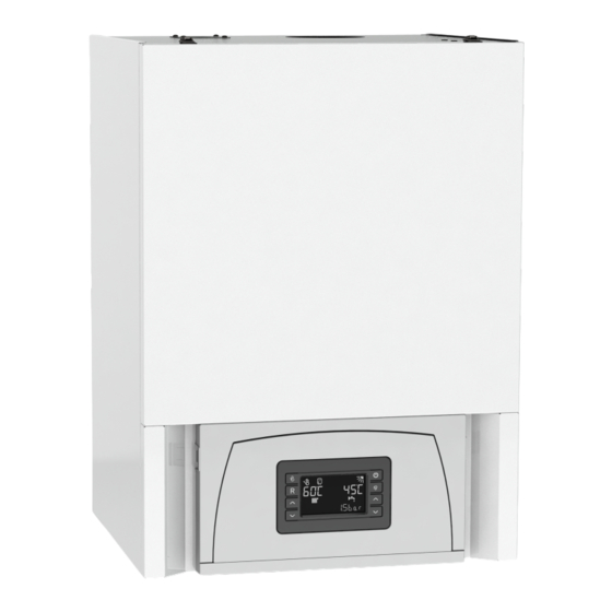
CONDENSING WALL-MOUNTED GAS BOILER
C38GC70V1
The image is for presentation only.
The product differs depending on the
model purchased, on the area and
the acquisition period.
2726
22
KÖBER SRL, Vaduri no.25, Alexandru cel Bun Commune, Neamt 617511, Roma-
nia
Tel.:+40.233.24.17.46, 233.24.19.33, Fax:+40.233.24.19.29
www.motan.ro
P M0 0 4 4 0 7
Advertisement
Table of Contents

Related Manuals for Kober C38GC70V1


Summary of Contents for Kober C38GC70V1
- Page 1 KÖBER SRL VADURI BRANCH USER MANUAL CONDENSING WALL-MOUNTED GAS BOILER C38GC70V1 The image is for presentation only. The product differs depending on the model purchased, on the area and the acquisition period. 2726 KÖBER SRL, Vaduri no.25, Alexandru cel Bun Commune, Neamt 617511, Roma- Tel.:+40.233.24.17.46, 233.24.19.33, Fax:+40.233.24.19.29...
-
Page 2: Table Of Contents
KÖBER SRL CONDENSING WALL-MOUNTED BOILERS C38GC70V1 VADURI BRANCH Contents SAFETY INSTRUCTIONS AND SYMBOLS ........................4 Validity of instructions ..................................4 CE marking ...................................... 4 Description and operation of the device ............................. 4 Intended use ....................................4 Product label ....................................4 DESCRIPTION OF THE BOILER ............................ - Page 3 KÖBER SRL CONDENSING WALL-MOUNTED BOILERS C38GC70V1 VADURI BRANCH 11.4.3 Central heating through the floor and radiators......................... 36 11.4.4 Central heating by radiators and coile water tank ......................36 11.4.5 Underfloor central heating and coil water tank ......................... 37 11.4.6 Mixed central heating (with radiators and underfloor) and coil water tank ..............37 11.4.7...
-
Page 4: Safety Instructions And Symbols
KÖBER SRL CONDENSING WALL-MOUNTED BOILERS C38GC70V1 VADURI BRANCH SAFETY INSTRUCTIONS AND SYMBOLS When installing the boiler, please follow the safety instructions in this manual! This manual is the property of KÖBER SRL- VADURI BRANCH. It is forbidden to copy or reproduce it without the written approval of KÖBER SRL-VADURI BRANCH. -
Page 5: Description Of The Boiler
Circulation pump Caution! The C38GC70V1 gas boiler is not equipped with an expansion tank; its installation and connection must be done by the installer. Installing the power plant in an installation without an expansion tank is not covered by the warranty! REV 01.08.2022... -
Page 6: Constructive And Functional Characteristics
KÖBER SRL CONDENSING WALL-MOUNTED BOILERS C38GC70V1 VADURI BRANCH Constructive and functional characteristics Tab. 2.2.1: Technical characteristics of the boiler model C38GC70V1: CONDENS 100 70 CH2 Name Type C38GC70V1 Gas category 2H3P (GN-G20 ; GPL-G31) Circulation Forced Combustion chamber Condensation **** Yield stars (dir. -
Page 7: Safety Instructions
Installation can only be performed by an authorized installer. It also takes responsibility for the correct installation and for the first commissioning. Carrying out the adjustment works as well as the maintenance and repair is allowed only to a company authorized and approved by KOBER SRL Vaduri. Danger! Danger to life due to poisoning and explosion due to leaks in the gas routes in case of irregular installation! Danger of damage when using improper tools. -
Page 8: Overall Dimensions And Mounting Position
+ 50 ° C or below 15 ° C. These substances can lead over time to the formation of corrosion in the appliance and in the air / gas intake / exhaust pipes. FIG. 4.2 Overall dimensions and mounting positions of thermal boiler model C38GC70V1: The legend:... -
Page 9: Minimum Required Distances / Free Spaces For Mounting
KÖBER SRL CONDENSING WALL-MOUNTED BOILERS C38GC70V1 VADURI BRANCH 4.3.2 Minimum required distances / free spaces for mounting Both for the installation / assembly of the boiler, and for carrying out subsequent maintenance works, need following minimum distances (fig. 4.3), respectively... -
Page 10: Installation
Technical Norms for the design and execution of natural gas supply systems). Boilers of the range C38GC70V1 are adjusted and tested in the factory for operation with GN-G20 natural gas. The gas connection is made of stainless steel pipe with an inner diameter of 16.4 mm. The gas supply line must not have a diameter smaller than the gas connection of the boiler. -
Page 11: Connecting The Boiler To The Heating Installation
The washing of the installation (new or old) is must be carried out through the service companies authorized and approved by KOBER SRL once it is put into operation. The defects appeared in the thermo-hydraulic circuit of the boiler, due to the non-washing of the installation (new or old) once it is put into operation, are not covered by the commercial warranty. -
Page 12: Condensate Drain Pipe Connection
KÖBER SRL CONDENSING WALL-MOUNTED BOILERS C38GC70V1 VADURI BRANCH Condensate drain pipe connection Danger! Danger to life due to flue gas leaks! The condensate drain pipe from the siphon must not be tightly connected to a sewage pipe, because otherwise the internal condensate siphon can be emptied by suction and the flue gases can enter the room where the boiler is installed. -
Page 13: Safety Valve Connection
KÖBER SRL CONDENSING WALL-MOUNTED BOILERS C38GC70V1 VADURI BRANCH The absence of water in the siphon causes emanations of the smoke evacuated in the ambient air. Safety valve connection Caution! Danger of scalding! The discharge valve of the safety valve (fig. 5.3) is connected to a drain pipe to the sewer. Otherwise there is a risk of flooding, which is not the responsibility of the boiler manufacturer. -
Page 14: Use Of Dual Kit
KÖBER SRL CONDENSING WALL-MOUNTED BOILERS C38GC70V1 VADURI BRANCH Caution! The kit must have a 3% (approximately 2 °) ascending slope on the exhaust side for condensate recovery, the slope is given by the position of the terminal. - at the mounting position of the terminal, it must be similar to the one in figure 5.7. Mounting it in another position can lead to the accumulation of water from precipitation in the combustion chamber of the boiler. -
Page 15: Use Of Vertical Coaxial Kit
KÖBER SRL CONDENSING WALL-MOUNTED BOILERS C38GC70V1 VADURI BRANCH Danger! It is forbidden to operate the boiler without air / gas intake / exhaust pipes, due to the fact that it endangers the life and health of people. The replacement will be made only by authorized personnel in accordance with the legislation in force, using original parts provided by the manufacturer. -
Page 16: Connection To The Electrical Network
KÖBER SRL CONDENSING WALL-MOUNTED BOILERS C38GC70V1 VADURI BRANCH Connection to the electrical network Danger! Danger to life due to electric shock to electrical contacts! The boiler must be connected to a single-phase network, provided with earthing, to ensure a stable voltage of 230 VAC +10% / - 15%, frequency 50 Hz, respecting the Phase-Zero polarity. -
Page 17: Connecting The Sensor To The External Boiler
KÖBER SRL CONDENSING WALL-MOUNTED BOILERS C38GC70V1 VADURI BRANCH Table 1 - Use of external sensor on the CH radiator circuit. 1 FACTORY SP05 T ° C heating flow T ° C obtained only if the heating temperature is set from the user interface (Tset CH = outside 80 °... -
Page 18: Filling And Emptying The Installation
KÖBER SRL CONDENSING WALL-MOUNTED BOILERS C38GC70V1 VADURI BRANCH Filling and emptying the installation Caution! The heating system must be washed before filling. Do not use antifreeze or corrosive agents as an additive for heating water! The company KÖBER SRL – VADURI BRANCH does not assume responsibility for the damages caused by this. - Page 19 KÖBER SRL CONDENSING WALL-MOUNTED BOILERS C38GC70V1 VADURI BRANCH Caution! Check the correct operation of the pump with non-fueled boiler. Operation of the boiler with the pump blocked can lead to melting of the venturi tube, error or damage to the main boiler derailleur.
-
Page 20: Operating Instructions - User Interface
KÖBER SRL CONDENSING WALL HEATING POWER PLANT C38GC45V1 VADURI BRANCH OPERATING INSTRUCTIONS - USER INTERFACE Control panel type LMC201 The LM201 control panel (fig.6.1) allows the visualization and modification of the parameters that define the operation of the boiler. Is made of: 8 touch keys (J1 ÷... -
Page 21: Description Of Functions And Graphical Contexts Displayed By Lmc1X Control Panel
KÖBER SRL CONDENSING WALL HEATING POWER PLANT C38GC45V1 VADURI BRANCH Table 6.2: Description of graphic symbols in the LCD display area Fig. 6.2 Control panel LMC202 display Annotation Description: Indicates whether the set operating mode is WINTER - active symbol Indicates the status of the "Vacation"... -
Page 22: Graphic Context - Boiler Start
KÖBER SRL CONDENSING WALL HEATING POWER PLANT C38GC45V1 VADURI BRANCH This will indicate the need to perform the PIF (Commissioning) operation by one of the service companies authorized according to the legislation in force and approved by us KÖBER SRL. For this, contact one of the partner companies within your domicile, indicated in the list inside the Warranty Certificate. -
Page 23: Graphic Context - Error Status
KÖBER SRL CONDENSING WALL HEATING POWER PLANT C38GC45V1 VADURI BRANCH When the domestic hot water demand is active, the symbol is active S11( )it will flash and the measured domestic hot water temperature will be displayed in the group of large digits on the right (D2). The symbols are also activatedS10 ( )- the presence of the flame andS13 ( )- boiler... -
Page 24: Graphic Context - Service Submenu
CONDENSING WALL HEATING POWER PLANT C38GC45V1 VADURI BRANCH The mandatory technical revision of VTP type is regulated by the specific ISCIR legislation and is not settled by KOBER SRL or by the service partner company. If you do not carry out the mandatory technical inspection of VTP type on time (every 2 years days +/- 2 weeks), in order to protect the thermal boiler from possible defects that are not covered by the warranty (clogging of heat exchangers and recuperators that can lead to their irremediable cracking;... -
Page 25: Starting The Boiler
KÖBER SRL CONDENSING WALL HEATING POWER PLANT C38GC45V1 VADURI BRANCH Starting the boiler 7.2.1 Starting the boiler To start the boiler, press the J5 key - (POWER)fig.7.5. Fig. 7.5 Control panel LMC201 Choice of operating mode in winter (district heating circuit) / summer (coil boiler with "sensor" control element) By pressing the J1 key ( ) you can change the operating mode from winter (district heating circuit) / summer (boiler with coil controlled by an external 3-way valve) and vice versa. -
Page 26: Preset Boiler Safety Functions
KÖBER SRL CONDENSING WALL HEATING POWER PLANT C38GC45V1 VADURI BRANCH Temperature regulation on the boiler circuit with coil - symbol S9 ( ) is displayed Setting the temperature of the water stored in the boiler - can only be done after connecting the sensor on the boiler to the boiler (see chap. -
Page 27: Switching Off The Boiler Safely
KÖBER SRL CONDENSING WALL HEATING POWER PLANT C38GC45V1 VADURI BRANCH After each shutdown of the boiler, the fan remains in operation for a period of time, in order to completely evacuate the flue gases from the boiler and with them, the water vapor they contain. In this way it protects both the electric control circuit of the fan and the primary heat exchanger, which cools partially. -
Page 28: Inspection And Maintenance
In order to keep the guarantee, please call the service company that performed the commissioning, in order to carry out the obligatory technical revision of VTP type. The obligatory technical revision of VTP type is regulated by the specific ISCIR legislation and is not settled by KOBER SRL or by the service partner company. -
Page 29: Description Of The Errors And The Way Of Troubleshooting Them
KÖBER SRL CONDENSING WALL HEATING POWER PLANT C38GC45V1 VADURI BRANCH DESCRIPTION OF THE ERRORS AND THE WAY OF TROUBLESHOOTING THEM Possible system errors are indicated by the following codes that appear on the display. The significance of the error signals that appear on the display is explained in table 9.1. -
Page 30: Disposal Of Electrical And Electronic Waste (Geo 5/2015)
SELF-RESETABLE when legislation in force and approved by us KOBER SRL. For this, cause disappears contact one of the partner companies within your domicile, indicated in the list inside the Warranty Certificate. -
Page 31: Annexes
CONDENSING WALL HEATING POWER PLANT C38GC45V1 VADURI BRANCH ANNEXES 11.1 Sketches necessary for installation and commissioning Types of mounting configurations for wall-mounted condensing boiler C38GC70V1 Exhaust type Exhaust piping - minimum and maximum length (m) Ø (mm) Lmin = 1m Lmax = 3 m Ø... - Page 32 KÖBER SRL CONDENSING WALL HEATING POWER PLANT C38GC45V1 VADURI BRANCH GARAGE, ANNEX, ETC. THE LEGEND: A - distance from under the window / hole ventilation = 300mm B - distance above the window / hole ventilation = 300mm C - left / right distance from window / vent hole = 300mm D, E - distance from the roof / drainage gutter = 250mm F - distance from the roof garage / balcony = 250mm...
-
Page 33: Hydraulic Characteristic Of The Pump
KÖBER SRL CONDENSING WALL HEATING POWER PLANT C38GC45V1 VADURI BRANCH 11.3 Hydraulic characteristic of the pump When designing the district heating installation, the hydraulic characteristics of the UPMXL 25-125 130 pump will be taken into account. Cuve Max. H 7.5 m 10 m 12.5 m 9.5 m... - Page 34 KÖBER SRL CONDENSING WALL HEATING POWER PLANT C38GC45V1 VADURI BRANCH The control of the pump is performed by adapting the differential pressure to the flow (proportional pressure and constant pressure). Unlike an uncontrolled pump, a constant pressure controlled pump maintains constant differential pressure. A pump with controlled proportional pressure reduces the differential pressure due to the decrease in heat demand.
-
Page 35: Operating Diagrams
PC – Circulation pump - - - Automation connections CMC1X – Boiler electronic board SC – Heat exchanger This note is informative! KOBER Ltd does not assume responsibility for its proper functioning. Heater network 11.4.2 Central underfloor heating Legend TA – Ambient thermostat with relay SE –... -
Page 36: Central Heating Through The Floor And Radiators
BA – Mixing bottle TI – Indication thermostat PI – Indication pressure gauge AA – Automatic aerator D- Distributor C- Collector This note is informative! KOBER Ltd does not assume Underfloor heating responsibility for its proper functioning. Heater network Mixing bottle 11.4.4... -
Page 37: Underfloor Central Heating And Coil Water Tank
KÖBER SRL CONDENSING WALL HEATING POWER PLANT C38GC45V1 VADURI BRANCH 11.4.5 Underfloor central heating and coil water tank Legend TA – Ambient thermostat with relay SE – External temp sensor TT – DH installation inlet RT – DH installation return A –... -
Page 38: Central Heating With Radiators, Coil Water Tank And Solar Collectors
KÖBER SRL CONDENSING WALL HEATING POWER PLANT C38GC45V1 VADURI BRANCH 11.4.7 Central heating with radiators, coil water tank and solar collectors Coiler water tank 11.4.8 Mixed central heating (with radiators and underfloor), coil water tank and solar collector Coiler water tank REV 01.05.2022 38 of 38...
Need help?
Do you have a question about the C38GC70V1 and is the answer not in the manual?
Questions and answers