Table of Contents
Advertisement
Quick Links
KÖBER SRL VADURI BRANCH
USER MANUAL
CONDENSING GAS BOILER
C38GC35-BA
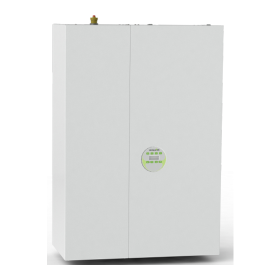
The image is for presentation
purpose. The product differs
depending on the purchased
model, the area and the
purchase period.
Condensing boiler
MKDens35 PLUS
(C38GC35-BA)
2726
21
Vaduri no.25, Alexandru cel Bun commune,
Neamt 617511, Romania Tel .: +40.233.24.17.46, 233.24.19.33, Fax: +40.233.24.19.29
www.motan.ro
Advertisement
Table of Contents

Subscribe to Our Youtube Channel
Related Manuals for Kober MKDens35 PLUS


Summary of Contents for Kober MKDens35 PLUS
- Page 1 The image is for presentation purpose. The product differs depending on the purchased model, the area and the purchase period. Condensing boiler MKDens35 PLUS (C38GC35-BA) 2726 Vaduri no.25, Alexandru cel Bun commune, Neamt 617511, Romania Tel .: +40.233.24.17.46, 233.24.19.33, Fax: +40.233.24.19.29 www.motan.ro...
-
Page 2: Table Of Contents
USER MANUAL CENTRAL HEATING BOILER TYPE C38GC35-BA Contents SECURITY INSTRUCTIONS AND SYMBOLS ........................3 Validity of instructions ..................................3 EC marking ...................................... 3 Use according to the destination ..............................3 DESCRIPTION OF THE BOILER ............................4 Structure ......................................4 Constructive and functional characteristics ..........................5 SAFETY INSTRUCTIONS .............................. -
Page 3: Security Instructions And Symbols
USER MANUAL CENTRAL HEATING BOILER TYPE C38GC35-BA SECURITY INSTRUCTIONS AND SYMBOLS When installing the boiler, please follow the safety instructions in this manual! This manual is the property of KÖBER SRL-SUCURSALA VADURI. It is forbidden to copy or reproduce it without the written approval of KÖBER SRL-SUCURSLA VADURI. -
Page 4: Description Of The Boiler
USER MANUAL CENTRAL HEATING BOILER TYPE C38GC35-BA DESCRIPTION OF THE BOILER 2.1 Structure The structure of the condensing wall-mounted thermal boiler C38GC35-BA Figure 2.1 Tab. 2.1Condensing wall-mounted boiler components 40L automatic boiler aerator Gas valve Boiler temperature sensor immersed District heating pressure sensor sheath Primary circuit... -
Page 5: Constructive And Functional Characteristics
USER MANUAL CENTRAL HEATING BOILER TYPE C38GC35-BA 2.2 Constructive and functional characteristics Tab. 2.2: Technical characteristics of the C38GC35-BA boiler. Name MKDENS35 Type C38GC35-BA I2H (GN-G20) Gas category Circulation Forced Combustion chamber Condensation **** Yield stars (dir. 92/42 / EEC) NOx class (G20) Energy efficiency class in district heating operation Energy efficiency class in operation on domestic hot water... -
Page 6: Safety Instructions
USER MANUAL CENTRAL HEATING BOILER TYPE C38GC35-BA SAFETY INSTRUCTIONS 3.1 Safety instructions 3.1.1 Installation and adjustment Installation can only be performed by an authorized installer. It also takes responsibility for the correct installation and for the first commissioning. Carrying out the adjustment works as well as the maintenance and repair is allowed only to an authorized company. -
Page 7: Overall Dimensions And Mounting Position
USER MANUAL CENTRAL HEATING BOILER TYPE C38GC35-BA 4.3 Overall dimensions and mounting position 4.3.1 Place of installation When choosing the installation location, please consider the following safety instructions: Warning! Do not install the boiler in areas endangered by frost! In case of frost the boiler can be damaged. These devices cannot be installed and used outdoors. -
Page 8: Minimum Required Distances / Free Spaces For Mounting
USER MANUAL CENTRAL HEATING BOILER TYPE C38GC35-BA 4.4 Minimum required distances / free spaces for mounting Both for the installation / assembly of the boiler, and for carrying out subsequent maintenance works, you need the following minimum distances (fig. 4.3), respectively minimum free spaces for installation: - distance from the front: 500 mm;... -
Page 9: Installation
USER MANUAL CENTRAL HEATING BOILER TYPE C38GC35-BA INSTALLATION Danger! Danger to life due to poisoning and explosion due to leaks in the gas path in case of faulty installation! The installation and commissioning of the device is allowed only to a company authorized according to the legislation in force for assembly and aggregates by KÖBER SRL- Vaduri Branch. -
Page 10: Gas Connection
USER MANUAL CENTRAL HEATING BOILER TYPE C38GC35-BA 5.2 Gas connection Danger! Danger to life due to poisoning and explosion due to leaks in the gas path in case of faulty installation! The installation of the gas part is only allowed by an authorized installer. It also takes responsibility for the correct installation and for the first commissioning. -
Page 11: Connecting The Boiler To The Domestic Hot Water Circuit
USER MANUAL CENTRAL HEATING BOILER TYPE C38GC35-BA 5.4 Connecting the boiler to the domestic hot water circuit The boiler is connected to the domestic hot water installation - through connections B and D (fig. 5.1). Warning! It is mandatory to install softener filters and a mechanical impurity filter on the cold water inlet connection. Warning! When installing the connection pipes, care must be taken not to strain them, in order to avoid leaks! The occurrence of pressure shocks (supply pressures higher than 3-4 bar simultaneously with the actuation of the... -
Page 12: Safety Valve Connection
USER MANUAL CENTRAL HEATING BOILER TYPE C38GC35-BA Discharge slope Discharge slope Fig. 5.4 – Condensate elimination in ventilated soil Fig. 5.5 - Condensate elimination in sewage Table 5.1 - Legend of figures 5.4 ÷ 5.6 1. Condensation siphon 2. Ventilation piping 3. - Page 13 USER MANUAL CENTRAL HEATING BOILER TYPE C38GC35-BA Slope 3% (approx. 2°) Fig. 5.7 Warning! The kit must have a 3% (approximately 2 °) ascending slope on the exhaust side for Fixing screws condensate recovery, the slope is given by the position of the terminal. Coaxial kit - at the mounting position of the terminal, it must be similar to the one in figure 5.7.
-
Page 14: Use Of Dual Kit
USER MANUAL CENTRAL HEATING BOILER TYPE C38GC35-BA 5.7.2 Use of dual kit The dual kit, fig. 5.9 is delivered only on request. The dual kit consists of two ducts: one for air intake and one for exhaust gases of the same diameter, Ø80mm, two 90-degree bends and the corresponding gaskets. The connection is made as follows (see figure no. -
Page 15: Connection To The Electrical Network
USER MANUAL CENTRAL HEATING BOILER TYPE C38GC35-BA Table 5.4 - Vertical kit Pos. Pbcs. Name.5. Flue gas exhaust pipe Ø 60 mm Centering profile Ø 60/100 mm Air intake pipe Ø 100 mm Roof mounting kit Ø 60/100 mm Gasket Ø 60 mm Gas exhaust pipe Ø... -
Page 16: Installation Of The Room Thermostat And The Outdoor Sensor
USER MANUAL CENTRAL HEATING BOILER TYPE C38GC35-BA Installation of the room thermostat and the outdoor sensor 5.9.1 Installing the room thermostat The procedure for coupling a temperature controller or an external sensor to the heating unit can be done EXCLUSIVELY by authorized personnel of the partner service companies approved by KÖBER SRL Vaduri Branch. - Page 17 USER MANUAL CENTRAL HEATING BOILER TYPE C38GC35-BA Table 1 - Use of external sensor on the CH radiator circuit. SP05 10 RECOMANDED SET T ° C T ° C heating flow outside obtained only if the heating temperature is set from the user interface (Tset CH = 80 ° C) Example of setting parameter SP 05: If the outside temperature = 0 °...
-
Page 18: Filling And Emptying The Installation
This will indicate the need to carry out the PIF (Commissioning) operation by one of the service companies authorized according to the legislation in force and approved by us KOBER SRL. For this, contact one of the partner companies within your domicile, indicated in the list inside the Warranty Certificate. - Page 19 USER MANUAL CENTRAL HEATING BOILER TYPE C38GC35-BA After unlocking the pump rotor, continue with the correct ventilation of the installation, by performing the steps described above. Warning! Improper ventilation of the installation can lead to irreparable damage to the primary heat exchanger - see figure 7.3.
-
Page 20: Electronic Control Module - User Interface, Operating Cycle
USER MANUAL CENTRAL HEATING BOILER TYPE C38GC35-BA ELECTRONIC CONTROL MODULE - USER INTERFACE, OPERATING CYCLE The control paneel LMC1112-C15 The control panel LMC1112-C1-15 (fig.6.1) allows the visualization and modification of the parameters that define the operation of the boiler. Is made of: 8 keys (J1 ÷... -
Page 21: Light Function
USER MANUAL CENTRAL HEATING BOILER TYPE C38GC35-BA Removing the boiler from error E88 requires: - breaking the boiler seal (self-destruct label on the left side / boiler cover). In order to grant the guarantee, this operation is allowed only to the personnel authorized and approved by KÖBER SRL. - removing the strap connected to the wires of the outdoor sensor (black cables). -
Page 22: Graphic Context - Adjustment Of Operating Parameters
In order to maintain the warranty, please call the service company that performed the start-up, in order to perform the PTI type mandatory technical inspection. The PTI type mandatory technical inspection is regulated by the specific ISCIR legislation and it is not reimbursed by KOBER LTD or by the partner service company. -
Page 23: Commissioning
USER MANUAL CENTRAL HEATING BOILER TYPE C38GC35-BA COMMISSIONING Danger! Commissioning works are allowed only to the authorized technician. In order to benefit from all the functions of the boiler for as long as possible, it is recommended to carry out all the works described below. -
Page 24: Heating Operation
USER MANUAL CENTRAL HEATING BOILER TYPE C38GC35-BA Instant DHW configuration with built-in boiler (parameter SP: 02 = 0 and SP: 04 = 1) - The Heating request is triggered by the detection by the flowmeter of a water flow. Thus the system tries to supply the user with domestic hot water at the set temperature. -
Page 25: User Training
The obligatory technical revision of VTP type is regulated by the specific ISCIR legislation and is not settled by the company KOBER SRL or by the service partner company. If you do not carry out the mandatory technical inspection of VTP type on time (every 2 years days +/- 2 weeks), in order to protect the thermal boiler from possible defects that are not covered by the warranty (clogging of heat exchangers and recuperators that can lead to their irremediable cracking;... -
Page 26: Maintenance Works
USER MANUAL CENTRAL HEATING BOILER TYPE C38GC35-BA It is mandatory that the periodic technical verification (VTP) be done according to the legislation in force. During the warranty period of the boiler, the periodic technical verification (VTP) will be done by companies approved by KÖBER SRL - VADURI BRANCH. -
Page 27: Description Of The Errors And Way Of Troubleshooting Them
USER MANUAL CENTRAL HEATING BOILER TYPE C38GC35-BA DESCRIPTION OF THE ERRORS AND WAY OF TROUBLESHOOTING THEM Possible system errors are indicated by the following codes that appear on the display. The significance of the error signals that appear on the display is explained in table 9.1. Note: I - information errors: these errors do not stop the operation of the boiler and are only displayed;... -
Page 28: Disposal Of Electrical And Electronic Waste (Geo 5/2015)
USER MANUAL CENTRAL HEATING BOILER TYPE C38GC35-BA Nonvol Code Class Meaning Reset mode atile -variations of the supply voltage / interruptions / gaps / frequency variations bigger / smaller than the standard ones manually resettable from the can lead, depending on the state of the boiler, to its RESET key permanent blocking in error E25. -
Page 29: Annexes
USER MANUAL CENTRAL HEATING BOILER TYPE C38GC35-BA ANNEXES 11.1 Wiring diagram FIG. REV. 01.08.2022 page 29 from 37... - Page 30 USER MANUAL CENTRAL HEATING BOILER TYPE C38GC35-BA Description of the symbols in the connection diagram Symbol Description 5 VDC power supply for logic circuits FBK_MOD Feedback for flame modulation FLUX Flowmeter for DHW circuit Flow switch Ionization sensor Programming connector Grounding Phase connector for 230 VAC power supply, 50 Hz Zero connector for 230 VAC power supply, 50 Hz...
-
Page 31: Hydraulic Characteristic Of Pump
USER MANUAL CENTRAL HEATING BOILER TYPE C38GC35-BA 11.2 Hydraulic characteristic of pump When designing the district heating system, the hydraulic characteristics of the pump will be taken into account. Pump graph Heating circuit PUMP FLOW Q[mc/h] Pump graph DHW circuit - boiler loading LED 1 Pump settings: The pump can be set to operate in four modes (4 stages). - Page 32 USER MANUAL CENTRAL HEATING BOILER TYPE C38GC35-BA Tab. 7.3 Significance of pump LEDs Performance in % of Display Meaning P1MAX 1 flashing green LED Standby (control from outside only) 1 green LED + 1 yellow LED Low performance 0-25 1 green LED + 2 yellow LEDs Low average performance 25-50 1 green LED + 3 yellow LEDs...
-
Page 33: Product Hydraulic Scheme
USER MANUAL CENTRAL HEATING BOILER TYPE C38GC35-BA 11.3 Product hydraulic scheme Fig. 10.2 LEGEND 1 - Automatic boiler aerator 2 - Boiler temperature sensor 3 - Heat exchanger overtemperature thermostat 18 - Heating circuit pump with vent valve 4 - 40L storage boiler 19 –... -
Page 34: Sketches Necessary For Installation And Commissioning
USER MANUAL CENTRAL HEATING BOILER TYPE C38GC35-BA 11.4 Sketches necessary for installation and commissioning Types of configurations for mounting, for wall-mounted condensing boiler C38GC25 Fig. 10.3 Exhaust piping minimum Exhaust type Ø (mm) maximum length (m) Lmin = 1m Lmax = 3m Ø... -
Page 35: Recommended Minimum Distances For Mounting The Coaxial Kit
USER MANUAL CENTRAL HEATING BOILER TYPE C38GC35-BA 11.5 Recommended minimum distances for mounting the coaxial kit Fig. 10.4.1 GARAGE, ANNEX, ETC. FIG. 10.4.2 THE LEGEND: A - distance from under the window / hole ventilation = 300mm B - distance above the window / hole ventilation = 300mm C - left / right distance from window / vent hole = 300mm... -
Page 36: Operating Scheme
USER MANUAL CENTRAL HEATING BOILER TYPE C38GC35-BA 11.6 Operating scheme 11.6.1 Central heating with radiators and domestic hot water preparation in instant regime – informative layout Legend TA – Ambient thermostat with relay SE – External temp sensor TT – DH installation inlet RT –... -
Page 37: Central Heating With Radiators + Floor And Domestic Hot Water Preparation Instantly - Informative Layout
USER MANUAL CENTRAL HEATING BOILER TYPE C38GC35-BA 11.6.3 Central heating with radiators + floor and domestic hot water preparation instantly – informative layout Legend C – Collector V3C – 3-way deviating electrical valve TA1, TA2 – Ambient thermostat with relay SE –...
Need help?
Do you have a question about the MKDens35 PLUS and is the answer not in the manual?
Questions and answers