Table of Contents

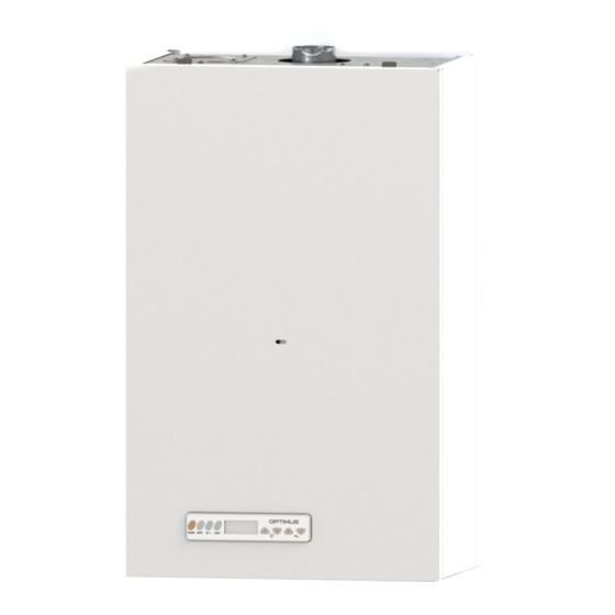
Summary of Contents for Kober C15SPV24MEFM
- Page 1 KÖBER SRL VADURI BRANCH USER MANUAL MURAL CENTRAL HEATING STATION C15SPV24MEFM C17SPV31MEF KÖBER SRL, no. 25 Vaduri, Alexandru cel Bun Commune, Neamt 617511, Romania Tel.:+40.233.24.17.46, 233.24.19.33, Fax:+40.233.24.19.29 www.motan.ro...
-
Page 2: Table Of Contents
USER MANUAL CENTRAL HEATING STATION TYPE C15SPV24MEFM / C17SPV31MEF Contents Safety instructions and symbols ..............................3 Valability of instructions ................................3 EC Marking ....................................3 Use according to destination ............................... 3 Safety instructions ..................................3 Instalation and adjustment ..................................3 Gas smell ........................................3 Changes in the area adjiacent to the heating station ........................3... -
Page 3: Safety Instructions And Symbols
This symbol indicates a necessary activity; Valability of instructions These instructions are valid exclusively for central heating station type C15SPV24MEFM / C17SPV31MEF. EC Marking EC marking applied on this product guarantees that the equipment complies with the esential conditions stipulated in the applicable European legislation: Directive regarding gas equipment 2009/142/CE (ex. -
Page 4: Technical And Functional Characteristics
USER MANUAL CENTRAL HEATING STATION TYPE C15SPV24MEFM / C17SPV31MEF Technical and functional characteristics Tab. 1 Functional and constructive characteristics Type C15SPV24MEFM C17SPV31MEF Commercial name OPTIMUS MAXOPTIMUS Energy efficiency symbol II2H3B/P; II2ELL3B/P II2H3B/P Usable gas category (GN-G20, G25; GPL-G30/G31) (GN-G20, GPL-G30/G31) -
Page 5: Mounting
USER MANUAL CENTRAL HEATING STATION TYPE C15SPV24MEFM / C17SPV31MEF Mounting Mounting set Check whether the mounting set is complete and undamaged – see table2. Tab. 2 Mounting set Pos. Name Item Station Station support Bag of small elements - it contains: - mounting screws 8x80 - 2 items. -
Page 6: Installation
USER MANUAL CENTRAL HEATING STATION TYPE C15SPV24MEFM / C17SPV31MEF 7.2.2 Minimum necessary distances/ free spaces for mounting Both for the mounting/ installation of the central heating stations and for later maintenance operations you will need the following minimum distances (fig. 1.3), respectively minimum free spaces for mounting: –... -
Page 7: Gas Connecting Pipe
In case parasite voltage appears on the gas pipe, it can be insulated by installing an electroinsulating piece (according to the Technical Norms for the planning and execution of natural gas input systems). Central heating boilers C15SPV24MEFM/C17SPV31MEF function on GN natural gas or liquefied gas GPL. -
Page 8: Connecting Pipe Of The Safety Valve
USER MANUAL CENTRAL HEATING STATION TYPE C15SPV24MEFM / C17SPV31MEF Connecting pipe of the safety valve Caution! Danger of hot water burns! The connecting pipe of the pressing of the safety valve is connected to the drain pipe to the sewage system. -
Page 9: Operation Instructions
USER MANUAL CENTRAL HEATING STATION TYPE C15SPV24MEFM / C17SPV31MEF Emptying the central heating station Emptying of the station implies the following: - turn off the station by pressing Power si switch off the electric power, close the gas tap; - close the thermal tap and the cold water input tap;... -
Page 10: Graphic Context - Station Startup
USER MANUAL CENTRAL HEATING STATION TYPE C15SPV24MEFM / C17SPV31MEF 9.1.2. Graphic context – station startup When started, the station is in an intermediary state for 5 seconds, necessary to initialise the system. During this interval the diplay shows only the message “On” on the S1 symbol on the interface (see figure 1.6). -
Page 11: Graphic Context - Service Submenu
Graphic context - Service submenu In the Service submenu, various functioning parameters of the central heating station can be viewed/ changed/ checked. This submenu can be accessed only by service personnel authorised by KOBER SRL Vaduri Branch, Central heating station startup To startup the station press POWER key fig.1.5. -
Page 12: Error Signals
USER MANUAL CENTRAL HEATING STATION TYPE C15SPV24MEFM / C17SPV31MEF Error signals Possible errors of the system are indicated by the following codes which appear on the display. Table 5: Meaning of error signals which appear on the display: Non- Code... -
Page 13: Station Switch Off In Safety Conditions
USER MANUAL CENTRAL HEATING STATION TYPE C15SPV24MEFM / C17SPV31MEF Station switch off in safety conditions If the user observes abnormal functioning of the equipment, if error codes are displayed repreatedly or if the user cannot understand the actions of the central heating station, the user must stop the functioning of the station immediately and in maximum safety conditions. -
Page 14: 10. Drawings Necessary For Mounting And Commissioning
USER MANUAL CENTRAL HEATING STATION TYPE C15SPV24MEFM / C17SPV31MEF 10. Drawings necessary for mounting and commissioning 10.1. Types of input-output configurations for mounting 10.2. Minimum distances for mounting the co-axial kit GARAGE, ANNEX, ETC LEGEND: A – distance under the window/ ventilation hole = 300mm B - distance over the window/ ventilation hole = 300mm C –... -
Page 15: Hydraulic Pump Characteristic
USER MANUAL CENTRAL HEATING STATION TYPE C15SPV24MEFM / C17SPV31MEF Hydraulic pump characteristic 10.3 When designing the thermal installation, the hydraulic pump characteristics need to be taken into consideration. Pump flow Q[mc/h] Pump setting: The pump can be set to function in four modes (4 steps). -
Page 16: Functioning Schemes Covered By Warranty
USER MANUAL CENTRAL HEATING STATION TYPE C15SPV24MEFM / C17SPV31MEF Functioning schemes covered by warranty 10.4 10.4.1 Central heating with radiators and instant preparation of hot water BOTTOM PLAN Legend : TA - Ambient thermostat SE - Exterior temperature sensor TT - Central heating Output... - Page 17 USER MANUAL CENTRAL HEATING STATION TYPE C15SPV24MEFM / C17SPV31MEF 10.4.3 Central heating with radiators and accumulated preparation of hot water (accummulation boiler) Legend : TA - Amb ie n t th e rmo sta t BOTTOM PLAN SE - Exte rio r te mp e ra tu re se n so r...


Need help?
Do you have a question about the C15SPV24MEFM and is the answer not in the manual?
Questions and answers