
Related Manuals for Atlas Copco XAS97 Dd


Summary of Contents for Atlas Copco XAS97 Dd
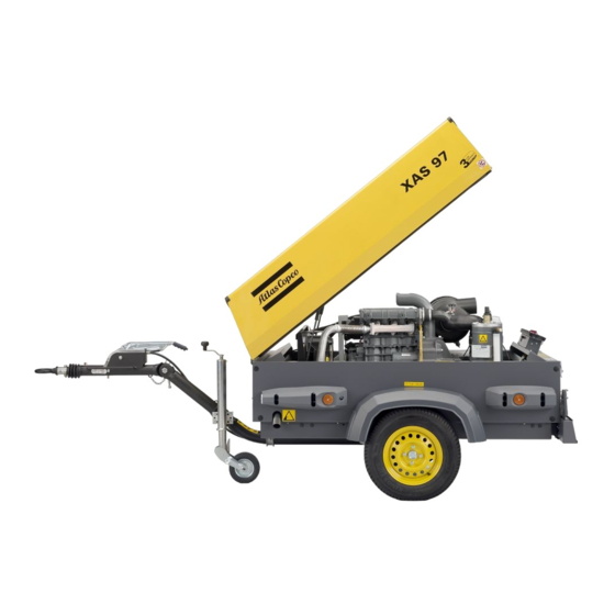
- Page 1 Instruction Manual for Portable Compressor XAS97 Dd Registration code Collection: APC X I Tab: Printed matter N° 2954 0950 00 ATLAS COPCO - PORTABLE AIR DIVISION www.atlascopco.com 01/2004...
- Page 2 Copyright 2004, Atlas Copco Airpower n.v., Antwerp, Belgium. Any unauthorized use or copying of the contents or any part thereof is prohibited. This applies in particular to trademarks, model denominations, part numbers and...
-
Page 3: Table Of Contents
Instruction Manual Follow the instructions in this booklet and we guarantee you years of troublefree operation. Please read the following instructions carefully before starting to use your machine. Always keep the manual available near the machine. In all correspondence always mention the compressor type and serial number, shown on the data plate. - Page 4 XAS97 Dd ONTENTS ONTENTS 4 Maintenance ................20 6 Problem solving ..............29 Use of service paks ........... 20 Alternator precautions..........29 Preventive maintenance schedule for the compressor ............ 20 7 Available options ..............32 Lubrication oils ............21 Oil level check ............21 8 Technical specifications ............
-
Page 5: Safety Precautions For Portable Compressors
To be read attentively and acted accordingly before towing, lifting, operating, performing maintenance or repairing the compressor NTRODUCTION The policy of Atlas Copco is to provide the users of their equipment with The manufacturer does not accept any liability for any damage arising from safe, reliable and efficient products. -
Page 6: Safety During Transport And Installation
If required, a lifting beam shall be applied between hoist and load. Atlas Copco Instruction Book (AIB). Keep fuel away from hot parts such as air outlet pipes or the engine exhaust. Do not smoke when fuelling. -
Page 7: Safety During Maintenance And Repair
16 Stationary housing guards are provided on all rotating or reciprocating parts not otherwise protected and which may be hazardous to personnel. Parts shall only be replaced by genuine Atlas Copco replacement parts. Machinery shall never be put into operation, when such guards have been All maintenance work, other than routine attention, shall only be removed, before the guards are securely reinstalled. -
Page 8: Tool Applications Safety
XAS97 Dd PECIFIC SAFETY PRECAUTIONS 18 When repair has been completed, the machine shall be barred over at least one revolution for reciprocating machines, several revolutions for rotary ones to ensure that there is no mechanical interference within the Batteries machine or driver. -
Page 9: Leading Particulars
AC, DIN, ball, ITA, GB, NATO (for options see chapter 7). The XAS97 Dd is a silenced, single-stage, oil-injected screw The braking system consists of an integrated parking brake and compressor, built for a nominal effective working pressure of 7 bar. -
Page 10: Markings And Information Labels
Danger, heat flat. Service every 24 hours. Warning! Electrocution hazard. Part under pressure. Atlas Copco mineral compressor oil. Do not stand on outlet valves. Atlas Copco synthetic compressor oil. Start-Stop indication of switch. Atlas Copco mineral engine oil. Do not run the motor with open doors. -
Page 11: Main Parts
Instruction Manual ARTS Fig. 2.2 Main parts of XAS97 Dd with some options Alternator Engine Oil Level Dipstick Jockey wheel Air Filter Engine Oil Filter (compressor element) Air outlet valves Exhaust Pipe Oil Filter (engine) Air Receiver Oil Level Gauge (compressor element) -
Page 12: Air Flow
XAS97 Dd OMPRESSOR EGULATING YSTEM Fig. 2.3 Air Filter Engine Oil Level Gauge Temperature Switch Air Receiver Oil Separator Unloader Assembly Air Outlet Valves Filler Plug Pressure Gauge Unloader Valve Blow Down Valve Flow Restrictor Regulating Valve Vent Hole Coupling... -
Page 13: Oil System
Instruction Manual IL SYSTEM ONTINUOUS REGULATING SYSTEM 2.3) 2.3) The system comprises: The system comprises: AR/OS Air receiver/oil separator Regulating valve Oil cooler Unloader assembly Oil filter Speed regulator The lower part of the air receiver (AR) serves as oil tank. The compressor is provided with a continuous regulating system. -
Page 14: Electrical System
Oil Pressure Switch Engine Starter Solenoid (part of M1) Lamptest Switch Shut-down Relay Temperature Switch Compressor Blocking Relay Fuel Solenoid Valve Override Start Relay Diode Start Relay Diode For location of relais K1, K2, K3, K4, see Atlas Copco Spare Parts List (ASL). -
Page 15: Description
Instruction Manual 2.8.2 D ESCRIPTION Operation of the electric circuit in detail Start button S1 position 1: Engine is running normally: Line 2 on 12V contact K3 closed (13-11), lamp H2 is on. K4 Oil pressure contact S3 opens, K3 no longer excited. K3 changes excites contact K4 (18-15). -
Page 16: Operating Instructions
XAS97 Dd OPERATING INSTRUCTIONS ARKING TOWING AND LIFTING INSTRUCTIONS When parking a compressor, secure support leg (1) or jockey wheel (2) to support the compressor in a level position. Be sure that the jockey wheel (2) is blocked by the blocking pin (6). -
Page 17: Towing Instructions
Instruction Manual 3.1.2 T 3.1.3 H OWING INSTRUCTIONS EIGHT ADJUSTMENT WITH ADJUSTABLE TOWBAR Before towing the compressor, ensure that the towing Before towing the compressor, make sure that the joints equipment of the vehicle matches the towing eye or ball of the towbar are secured with maximum strength connector, and ensure that the hood is closed and locked without damaging the towbar. -
Page 18: Lifting Instructions
XAS97 Dd 3.1.4 L IFTING INSTRUCTIONS EFORE STARTING 1. Before initial start-up, prepare battery for operation if not already done. See section 4.8. 2. With the compressor standing level, check the level of the engine oil. Add oil, if necessary, to the upper mark on dipstick. Consult the Engine Operation Manual for the type and viscosity grade of the engine oil. -
Page 19: Starting/Stopping
Instruction Manual TARTING TOPPING Without cold start Hourmeter Circuit breaker button Working pressure gauge Temperature alarm lamp (red) General alarm lamp (red) Contact switch Lamp test With cold start (option) Cold start button Fig. 3.10 Control panel Fault situations and protective devices: Before starting make sure, the electrical circuit is not interrupted by the circuit breaker (F1), located at the bottom of the control panel –... -
Page 20: Maintenance
When servicing, replace all disengaged packings, e.g. gaskets, O-rings, washers. Order Service Paks at your local Atlas Copco dealer. For engine maintenance refer to Engine Operation Manual. The maintenance schedule has to be seen as a guideline for units operating in a dusty environment typical to compressor applications. -
Page 21: Lubrication Oils
Operation Manual and top up with oil if necessary. If you want to use another brand of oil, consult the engine instruction manual. It is strongly recommended to use Atlas Copco branded lubrication oils for the compressor. If you want to use 4.4.2 C HECK COMPRESSOR OIL LEVEL another brands of oil, consult Atlas Copco. -
Page 22: Oil And Oil Filter Change
The prescribed interval (see section 4.2) is based on an oil temperature of up to 100 °C and normal operating conditions. When operating in high ambient temperatures, in very dusty or high humidity conditions, it is recommended to change the oil more frequently. In this case, contact Atlas Copco. -
Page 23: Cleaning Coolers
Instruction Manual LEANING COOLERS LEANING FUEL TANK Observe all relevant environmental and safety precautions. Place an appropriate drain pan under the drainplug (Fig. 2.2, DP of the fuel tank. Remove the drain plug. Lift the towbar (Fig. 2.2, TB) and tilt the compressor approx. 15° to remove all fuel, dirt and water. -
Page 24: Activating A Dry-Charged Battery
When The order number of the Service Paks are listed in the Atlas Copco charging batteries, each cell must be open, i.e. plugs and/or cover Parts List (ASL). -
Page 25: Adjustments And Servicing Procedures
Instruction Manual ADJUSTMENTS AND SERVICING PROCEDURES DJUSTMENT OF THE CONTINUOUS REGULATING SYSTEM Fig. 5.1 The working pressure is determined by the tension of the spring in the regulating valve (RV). This tension can be increased to raise the pressure and decreased to lower it by turning the adjusting wheel clockwise and anti-clockwise respectively. -
Page 26: Air Filter Engine/Compressor
5.2.2 R ECOMMENDATIONS IR RECEIVER The Atlas Copco air filters are specially designed for The air receiver is tested according to official standards. Regularly the application. The use of non-genuine air filters may have inspections carried out in conformity with local regulations. -
Page 27: Fuel System
Instruction Manual 5.6.1 B UEL SYSTEM RAKE SHOE ADJUSTMENT Check the thickness of the brake lining. Remove both black plastic plugs (5), one on each wheel. When the brake lining has been worn to a thickness of 1 mm or less, the brake shoes have to be replaced. After inspection and/or replacement re-insert both plugs. -
Page 28: Test Procedure Of Brake Cable Adjustment
XAS97 Dd 5.6.2 T 5.6.3 B EST PROCEDURE OF BRAKE CABLE RAKE CABLE ADJUSTMENT ADJUSTMENT 1. Check if the towing eye rod of the overrun brake mechanism is in the outmost position. 2. Check if the adjustable towbar (= option) is in the actual towing position. -
Page 29: Problem Solving
If it’s not possible to solve the problem with this 4. Never operate the engine without the main or voltage sensing problem solving table, please consult Atlas Copco. cables connected in the circuit. Problem... - Page 30 Speed regulation cable maladjusted; see section 5.1. d. Engine does not run at max. speed. d. Check the maximum speed, service the fuel filter. e. Oil separator element (OS) clogged. e. Have element removed and inspected by an Atlas Copco Service representative.
- Page 31 15. Air and oil mist expelled from a. Unloader valve (UV) defective. a. Repair valve. air filter after stopping. b. Wrong oil type (without foam-retarding additives). b. Consult Atlas Copco. 16. Compressor overheating. a. Insufficient compressor cooling. a. Relocate compressor. b. Oil cooler (OC) clogged externally.
-
Page 32: Available Options
XAS97 Dd AVAILABLE OPTIONS The XAS97 Dd can be delivered with following options: Pressure vessel approval: ASME Undercarriage: Adjustable with brakes Adjustable without brakes Fixed with brakes Fixed without brakes Support (without undercarriage) Towing eyes: Atlas Copco Ball Italian GB 50 mm... -
Page 33: Technical Specifications
Instruction Manual TECHNICAL SPECIFICATIONS OMPRESSOR ENGINE SPECIFICATIONS ORQUE VALUES Compressor type Designation Unit 8.1.1 F OR GENERAL APPLICATIONS Reference conditions The following tables list the recommended torques applied for 1. Absolute inlet pressure general applications at assembly of the compressor. 2. -
Page 34: Conversion List Of Si Units Into British Units
XAS97 Dd ONVERSION LIST OF UNITS INTO RITISH Design data Compressor UNITS 1. Number of compression stages 1 bar 14.504 psi 0.035 oz Engine 1 kg 2.205 lb 1. Make 1 km/h 0.621 mile/h 2. Type F3M2011 1 kW 1.341 hp (UK and US) 3. - Page 36 Instruction Manual for Portable Compressor XAS97 Dd...
Need help?
Do you have a question about the XAS97 Dd and is the answer not in the manual?
Questions and answers