Table of Contents
Advertisement
Quick Links
Advertisement
Table of Contents

Related Manuals for Airflow AIROVENT MEV WH4H CENTRAL EXTRACT


Summary of Contents for Airflow AIROVENT MEV WH4H CENTRAL EXTRACT
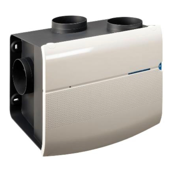
- Page 1 AIROVENT RF MEV WH4H CENTRAL MECHANICAL EXTRACT VENTILATION UNIT WITH BUILT-IN HUMIDITY SENSOR Installation / Operation and Service Guide For unit versatility it is supplied without a controller. A choice of controllers is available at www.airflow.com Page 1 of 28...
-
Page 2: Table Of Contents
Contents Introduction ................3 Unit Dimensions (mm) ............. 4 Unit Specifications ..............5 Safety Information and Guidance ..........6 Transport and Storage ............. 7 Electrical Installation ..............8 ....................8 PCB Main Features ..............9 Mechanical Installation ............10 Duct Connections ..............13 Pairing RF Controllers to Unit .......... -
Page 3: Introduction
Each remote control is intended for exclusive use with Airflow AIROVENT RF MEV WH4H Central Extract Units. If bought separately, the remote control must be connected for the first time to the Airflow ventilation unit by the installer. Page 3 of 28... -
Page 4: Unit Dimensions (Mm)
Unit Dimensions (mm) Air from wet rooms Air to outside Page 3 of 28 Page 4 of 28... -
Page 5: Unit Specifications
Unit Specifications Page 5 of 28... -
Page 6: Safety Information And Guidance
Safety Information and Guidance IMPORTANT! Read these instructions carefully before installing this Mechanical Central Extract Unit. This manual covers the operation of the AIROVENT RF MEV WH4H MECHANICAL EXTRACT UNIT WITH BUILT-IN HUMIDITY SENSOR only. It must therefore be read in conjunction with the relevant AIROVENT RF MEV WH4H CONTROLLER User Manual. -
Page 7: Transport And Storage
Any damage to the fan or packaging should be inspected by a suitably qualified person or returned to Airflow Developments Ltd for inspection before use. Fans should not be lifted or carried by an electrical lead, if fitted. -
Page 8: Electrical Installation
Electrical Installation All electrical installations must be carried out by an approved electrician in accordance with the latest IET BS7671 Requirements for Electrical Installation, Low Voltage Directive 2014/35/EU, Machinery Directive 89/392/CE, or the appropriate regulations in the country of installation. All fans require a 240V 50 Hz single phase supply. - Page 9 Immediately switch off the fan should any problems be found, and contact Airflow Developments Ltd. Fan motors used are suitable for continuous running and have a rated duty type S1 (motor is suitable to this duty type and rating at which the fan may be operated for an unlimited period).
-
Page 10: Pcb Main Features
PCB Main Features Red/ Green Push button Mains Power in (230V – 50 Cable to RF Dip switches – 1Ph) Receiver Page 10 of 28... -
Page 11: Mechanical Installation
Units should be installed to a sufficiently solid structure giving adequate support. Fixings suitable for the mounting surface should be used. Airflow Developments Rubber mount (Part No: 90001294) can be used to help protect against mechanical noise transmission into the mounting surface. - Page 12 Fig.1 – Top Cover Locking Tabs Fig.2 – Mounting Slots Fig.3 – Fan housing lifting handles Page 12 of 28...
-
Page 13: Duct Connections
Duct Connections This unit has three Ø125m and one Ø125/ 160mm diameter ports moulded on the extract duct connection box. Three ports are sealed off with blanking plates. The Ø125/ 160mm diameter port offers a choice of duct size, this is to help duct system pressure on higher airflows. Care should be taken when removing the Ø125mm diameter port and membrane to ensure no excess force is used which could cause irreputable damage. -
Page 14: Pairing Rf Controllers To Unit
Final connections can be made with a short length of flexible ducting (Part No. 52641009) and the correct sealing clamps (Part No. 51849403). The use of excessive amounts of flexible ducting will result in high system pressures and a noisy system. Ridged duct connections should be sealed with a non-hardening sealant (Part No. - Page 15 When electric power to the unit is re-installed the LED on the PCB will flash red and green (PCB Main Features – Page 10) and then remain green for 3 minutes. In this is the time RF controllers can be paired to the unit. Please refer to the instruction leaflet included with the controller purchased with this unit and follow the pairing instructions provided.
-
Page 16: Fan Performance Settings
Fan Performance Settings This unit has two airflow performance curves to choose from. Each performance curve is broken down into three bands, low, medium, and high. Each band has several fan speeds to choose from. All of which can be set by adjusting the dip switch settings. -
Page 17: Dip Switch Settings - Table A
Dip Switch Settings - Table A Page 17 of 28... -
Page 18: Dip Switch Settings - Table B
Dip Switch Settings – Table B Page 18 of 28... -
Page 19: Flow / Pressure Graph A
Flow / Pressure Graph A Page 19 of 28... -
Page 20: Flow / Pressure Graph B
Flow / Pressure Graph B Page 20 of 28... -
Page 21: Service And Maintenance
Failure to do so causes excess system pressure which will reduce the systems airflow, make the system noisier and ultimately lead to fan unit failure. To clean the unit, firstly remove the unit’s white, top protective cover held on by the locking tabs –... - Page 22 After re-connecting the electrical supply, the unit should be switched on. If there is any undue noise, switch the unit off immediately and the fault rectified. If the fault cannot be found contact Airflow Developments Ltd for advice at info@airflow.com. Page 22 of 28...
-
Page 23: Unit & Packaging Disposal
Unit & Packaging Disposal These fan units consist mainly of steel, iron, aluminium, copper, electrical insulation materials, cables, wires, and plastic. Complete fans and parts that are at end of life due to wear and tear, corrosion, fatigue and or other effects that cannot be discerned must be disposed of in the correct manner conforming to local and / or international guidelines and regulations. -
Page 24: Assorted Accessories
Assorted Accessories Page 24 of 28... -
Page 25: Warranty
Applicable to units installed and used in the UNITED KINGDOM. Warranty covers the fan and not reinstallation if required. In the event of any defective parts being found, Airflow Developments Ltd reserves the right to repair, or at our discretion, replace without charge, provided the unit has... - Page 26 Airflow Developments Ltd shall not be liable for any loss, injury, or other consequential damage, in the event of a failure of the equipment, arising from, or in connection with, the equipment excepting only that nothing in this condition shall be construed as to exclude or restrict liability for negligence.
- Page 27 Unit Service Notes Page 27 of 28...
- Page 28 Unit Service Notes Page 28 of 28...
Need help?
Do you have a question about the AIROVENT MEV WH4H CENTRAL EXTRACT and is the answer not in the manual?
Questions and answers