Advertisement
Quick Links
Advertisement

Subscribe to Our Youtube Channel
Related Manuals for Airflow Aventa Silent 100


Summary of Contents for Airflow Aventa Silent 100
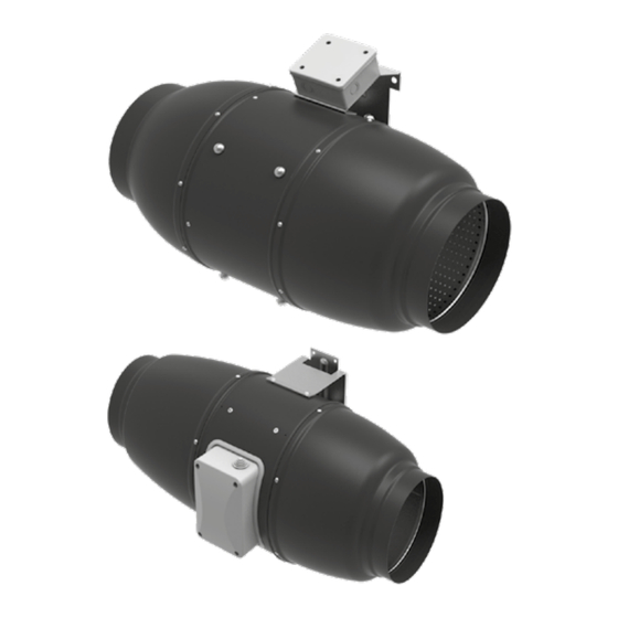
- Page 1 INLINE FANS IN SOUND-INSULATED CASING Aventa Silent USER’S MANUAL www.airflow.com...
- Page 2 CONTENTS Safety requirements ............................................3 Delivery set ................................................9 Operation guidelines ............................................9 Brief description ..............................................9 Product sales ................................................. 9 Designation key ..............................................11 Installation and set-up............................................. 12 Connection to power mains ........................................18 Electronics operation algorithm ....................................... 23 Technical maintenance ...........................................
- Page 3 SAFETY REQUIREMENTS This unit is not intended for use by persons (including children) with reduced physical, sensory or mental capabilities, or lack of experience and knowledge, unless they have been given supervision or instruction concerning use of the unit by a person responsible for their safety. Children should be supervised to ensure that they do not play with the unit.
- Page 4 Connection to the mains must be made through a disconnecting device, which is integrated into the fixed wiring system in accordance with the wiring rules for design of electrical units, and has a contact separation in all poles that allows for full disconnection under overvoltage category III conditions.
- Page 5 back flow of combustion gases does not occur. Fixing means for attachment to the ceiling such as hooks or other devices shall be fixed with a sufficient strength to withstand 4 times the weight of the appliance. The mounting of the suspension system shall be performed by the manufacturer, its service agent or suitably qualified persons.
- Page 6 All operations described in this manual must be performed by qualified personnel only, properly trained and qualified to install, make electrical connections and maintain ventilation units. Do not attempt to install the product, connect it to the mains, or perform maintenance yourself. This is unsafe and impossible without special knowledge.
- Page 7 Check the unit for any visible damage of the impeller, the casing, and the grille before starting installation. The casing internals must be free of any foreign objects that can damage the impeller blades. While mounting the unit, avoid compression of the casing! Deformation of the casing may result in motor jam and excessive noise.
- Page 8 The Company reserves the right to modify the technical characteristics, design, or configuration of its products at any time in order to incorporate the latest technological developments. Never touch the unit with wet or damp hands. Never touch the unit when barefoot. BEFORE INSTALLING ADDITIONAL EXTERNAL DEVICES, READ THE RELEVANT USER MANUALS.
- Page 9 DELIVERY SET 1 pc. Screws with dowels 4 pcs. Plastic screwdriver (only for the models with a timer) 1 pc. User’s manual 1 pc. Packing box 1 pc. OPERATION GUIDELINES The fan is rated for connection to single-phase AC 220-240 V/50 Hz or 220 V/60 Hz power mains. The unit is rated for continuous operation.
- Page 10 Overall dimensions Ø D Aventa Silent 100 Aventa Silent 125 Aventa Silent 150 Aventa Silent 160 Aventa Silent 200 Aventa Silent 250 Aventa Silent 315...
- Page 11 Aventa Silent 100/125/160 Aventa Silent 150 Aventa Silent 200/250/315 øD H øD H øD H...
- Page 12 INSTALLATION AND SET-UP The fan is suitable both for horizontal or vertical mounting on the floor, on the wall or on the ceiling. While mounting the fan, provide extra protection against water ingress, such as: • For the top mounting install an outer protecting hood above. •...
- Page 13 Cut off power supply and make sure electricity Lead the power cable to the ventilation hole, drill the has been turned off. Mark the holes for fixing the mounting holes and install the dowels. fan and the power cable. For any mounting position connect an air duct on both Fix the fan with the screws.
- Page 14 Cut off power supply and make sure electricity has been turned off. Remove the cover of the fan. Connect the power cord wires to the terminal block and Supply power to the fan. assemble the fan in reverse order.
- Page 15 Mounting sequence for different fan models...
- Page 17 Aventa Silent ... T Aventa Silent ... RV 2 min 30 min STOP Aventa Silent ... U (U1, U2, Un, U1n, U2n) Aventa Silent ... P Thermostat control knob Speed Speed control knob control knob...
- Page 18 CONNECTION TO POWER MAINS The fan is rated for connection to single-phase AC 220-240 V/50 (60) Hz power mains. TERMINAL DESIGNATIONS ON WIRING DIAGRAMS L1 — minimum speed terminal S — external speed controller L2 — maximum speed terminal ST — external switch QF —...
- Page 19 Aventa Silent 100/125 Max/min...
- Page 20 Aventa Silent 150/160/200/250/315 Max/min...
- Page 21 Aventa Silent ... T terminal block for 4 contacts terminal block for 5 contacts Max/min terminal block for 5 contacts terminal block for 4 contacts...
- Page 22 terminal block for 5 contacts terminal block for 4 contacts...
- Page 23 ELECTRONICS OPERATION ALGORITHM It is possible to control the fan rotation speed without options by voltage, as well as by thyristor controllers. The speed controller is purchased separately. Warning! When adjusting the voltage, make sure there is no unusual noise or vibration at reduced motor speed. The motor current may exceed the rated current during voltage regulation.
- Page 24 The terminal compartment incorporates 2 control knobs: • presetting the speed • setting the threshold for the electronic thermostat The thermostat operation indicator is located on the fan cover. It lights up when the air temperature exceeds the set value. To set the thermostat threshold, turn the temperature knob clockwise to increase the value and counter-clockwise to decrease the value.
- Page 25 TECHNICAL MAINTENANCE The fan maintenance periodicity is at least once per 6 months. Maintenance steps: Disconnect the fan from power supply and make sure Clean the fan with a soft dry cloth or a brush. electricity has been turned off. Disconnect an air duct on both sides of the fan.
- Page 26 Problem Possible reasons Troubleshooting Make sure the power supply line No power supply. is connected correctly, otherwise When the unit is connected to power troubleshoot the connection error. mains, the fan does not rotate and does not respond to any controls. Internal connection fault.
- Page 27 MANUFACTURER’S WARRANTY The product is in compliance with EU norms and standards on low voltage guidelines and electromagnetic compatibility. We hereby declare that the product complies with the provisions of Electromagnetic Compatibility (EMC) Directive 2014/30/ EU of the European Parliament and of the Council, Low Voltage Directive (LVD) 2014/35/EU of the European Parliament and of the Council and CE-marking Council Directive 93/68/EEC.
- Page 28 • Redesign or engineering changes to the unit. • Replacement and use of any assemblies, parts and components not approved by the manufacturer. • Unit misuse. • Violation of the unit installation regulations by the user. • Violation of the unit control regulations by the user. •...
- Page 31 Quality Inspector’s Stamp Sold by (name and stamp of the seller) Manufacture Date Purchase Date...
- Page 32 Certificate of acceptance Aventa Silent___________________________________ The fan is recognized as serviceable Airflow97EN-06...
Need help?
Do you have a question about the Aventa Silent 100 and is the answer not in the manual?
Questions and answers