
Related Manuals for EUCHNER CTP-AR Unicode


Summary of Contents for EUCHNER CTP-AR Unicode
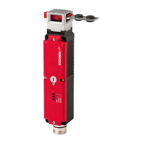
- Page 1 Operating Instructions Transponder-Coded Safety Switch With Guard Locking CTP-AR Unicode/Multicode...
-
Page 2: Table Of Contents
Operating Instructions Transponder-Coded Safety Switch CTP-AR Contents About this document ..................... 4 1.1. Scope ............................4 1.2. Target group ..........................4 1.3. Key to symbols ..........................4 1.4. Supplementary documents ......................4 Correct use ......................5 Description of the safety function ................6 Exclusion of liability and warranty ................. 8 General safety precautions ................... - Page 3 Operating Instructions Transponder-Coded Safety Switch CTP-AR 10.5. Maximum cable lengths .........................19 10.5.1. Determining cable lengths using the example table ............20 10.6. Connector assignment of safety switch CTP-…-AR-…-SAB-… with plug connectors 2 x M12 ....21 10.7. Connector assignment of safety switch CTP-…-AR-…-SH-… with plug connector M23 (RC18) .....21 10.8.
-
Page 4: About This Document
Important! Always read all documents to gain a complete overview of safe installation, setup and use of the device. The documents can be downloaded from www.euchner.com. For this purpose enter the doc. no. in the search box. (translation of the original operating instructions) 2123041-08-01/21... -
Page 5: Correct Use
Ì EN 60204-1 The safety switch is allowed to be operated only in conjunction with the intended EUCHNER actuator and the related connec- tion components from EUCHNER. On the use of different actuators or other connection components, EUCHNER provides no warranty for safe function. -
Page 6: Description Of The Safety Function
Operating Instructions Transponder-Coded Safety Switch CTP-AR NOTICE For information about combination with an AR evaluation unit, please refer to chapter 10.10. Connection of several CTP‑AR in a switch chain on page 24. 3. Description of the safety function Devices from this series feature the following safety functions: Monitoring of guard locking and the position of the guard (interlocking device with guard locking according to EN ISO 14119) Ì... - Page 7 Operating Instructions Transponder-Coded Safety Switch CTP-AR Control of guard locking If the device is used as guard locking for personnel protection, the control of the guard locking must be regarded as a safety function. The device does not feature a safety characteristic for the control of the guard locking, because the guard locking solenoid is completely disconnected from outside the device (no control function within the device).
-
Page 8: Exclusion Of Liability And Warranty
Prior to use, read the operating instructions and keep these in a safe place. Ensure the operating instructions are always available during mounting, setup and servicing. For this reason you should archive a printed copy of the operating instructions. You can download the operating instructions from www.euchner.com. (translation of the original operating instructions) 2123041-08-01/21... -
Page 9: Function
Operating Instructions Transponder-Coded Safety Switch CTP-AR 6. Function The device permits the locking of movable guards. Transponder-coded actuator The system consists of the following components: coded actuator (transponder) and switch. Whether the device learns the complete actuator code (unicode) or not (multi- code) depends on the respective version. -
Page 10: Guard Locking On Version Ctp-L2
Operating Instructions Transponder-Coded Safety Switch CTP-AR The actuator cannot be pulled out of the switch and the guard is locked as long as the guard locking pin is extended. If a voltage is applied to the guard locking solenoid, the guard locking pin is retracted and the actuator is released. The guard can be opened. -
Page 11: Manual Release
Operating Instructions Transponder-Coded Safety Switch CTP-AR 7. Manual release Important! No further release functions can be retrofitted on Extended variants with control elements in position 1 (S1) and position 2 (S2). Some situations require the guard locking to be released manually (e.g. malfunctions or an emergency). A function test should be performed after release. -
Page 12: Emergency Release
Operating Instructions Transponder-Coded Safety Switch CTP-AR 7.2. Emergency release Permits opening of a locked guard from outside the danger zone without tools. For mounting, see the mounting supplement. Important! Ì It must be possible to operate the emergency release manually from outside the protected area without tools. -
Page 13: Wire Front Release (Bowden)
Operating Instructions Transponder-Coded Safety Switch CTP-AR 7.4. Wire front release (bowden) Release via a pull wire. Depending on the type of attachment, the wire front release can be used as an emergency release or escape release. The following applies to non-latching wire front releases: If the release is to be used as an emergency release, one of the following measures must be taken (see EN ISO 14119:2013, section 5.7.5.3): Ì... -
Page 14: Changing The Approach Direction
Operating Instructions Transponder-Coded Safety Switch CTP-AR 8. Changing the approach direction The approach direction needs to be changed only if the switch is to be approached from the rear. Proceed as follows: 1. Remove the screws from the safety switch 2. -
Page 15: Mounting
UV radiation or corrosion) must be checked before a guard locking device is used. Ì Contact EUCHNER if you have any questions about environmental influences or about use in ag- gressive environments. A clearance of 12 mm must be maintained around the actuator head (see Figure 2). -
Page 16: Electrical Connection
The following connection options are available: Ì Separate operation Ì Series connection with Y-distributors from EUCHNER (only with M12 plug connector) Ì Series connection, e.g. with wiring in the control cabinet Ì Operation on an AR evaluation unit (only for CTP Extended). -
Page 17: Notes About
Operating Instructions Transponder-Coded Safety Switch CTP-AR 10.1. Notes about Important! Ì This device is intended to be used with a Class 2 power source in accordance with UL1310. As an alternative an LV/C (Limited Voltage/Current) power source with the following properties can be used: This device shall be used with a suitable isolating source in conjunction with a fuse in accordance with UL248. -
Page 18: Requirements For Connecting Cables
Ì On the use of other connection components, the requirements in the following table apply. EUCHNER provides no warranty for safe function in case of failure to comply with these require- ments. Observe the following requirements with respect to the connecting cables: For safety switch CTP-…-AR-…-SAB-…... -
Page 19: Maximum Cable Lengths
Operating Instructions Transponder-Coded Safety Switch CTP-AR 10.5. Maximum cable lengths Switch chains are permitted up to a maximum overall cable length of 200 m taking into account the voltage drop as a result of the cable resistance (see table below with example data and case example). =200 m = 24 V -20% = 24 V -10%... -
Page 20: Determining Cable Lengths Using The Example Table
Operating Instructions Transponder-Coded Safety Switch CTP-AR 10.5.1. Determining cable lengths using the example table Example: 6 switches are to be used in series. Cabling with a length of 40 m is routed from a safety relay in the control cabinet to the last switch (#6). Cables with a length of 20 m each are connected between the individual CES-AR/CTP-L1-… safety switches. -
Page 21: Connector Assignment Of Safety Switch Ctp
X 2.3 Diagnostic monitoring output X 2.4 Solenoid operating voltage, 24 V DC X 2.5 n. c. 1) Only for standard EUCHNER connecting cable. 10.7. Connector assignment of safety switch CTP-…-AR-…-SH-… with plug connector M23 (RC18) Wiring diagram B Conductor coloring Plug connector... -
Page 22: Connector Assignment Of Y-Distributor
Operating Instructions Transponder-Coded Safety Switch CTP-AR 10.8. Connector assignment of Y-distributor (Only for version with plug connectors 2 x M12) Connector assignment of safety switch CTP-L1-… (plug X1, 8-pin plug) and Y-distributor (8-pin socket) Function X1.1 FI1B X1.2 X1.3 FO1A X1.4 FO1B X1.5... -
Page 23: Connection Of A Single Ctp-Ar
The user is responsible for safe inte- gration into the overall system. Detailed application examples can be found at www.euchner.com. Simply enter the order number of your switch in the search box. You will find all available connec- tion examples for the device in Downloads. -
Page 24: Connection Of Several Ctp-Ar In A Switch Chain
The user is responsible for safe inte- gration into the overall system. Detailed application examples can be found at www.euchner.com. Simply enter the order number of your switch in the search box. You will find all available connec- tion examples for the device in Downloads. - Page 25 Operating Instructions Transponder-Coded Safety Switch CTP-AR Figure 5: Connection example for operation in a CES-AR switch chain 2123041-08-01/21 (translation of the original operating instructions)
-
Page 26: Information On Operation On An Ar Evaluation Unit
Ì Always connect inputs FI1A and FI1B directly to a power supply unit or to outputs FO1A and FO1B of another EUCHNER AR device (series connection). Pulsed signals must not be present at inputs FI1A and FI1B. - Page 27 Operating Instructions Transponder-Coded Safety Switch CTP-AR Figure 6: Connection example for the connection to ET200 2123041-08-01/21 (translation of the original operating instructions)
-
Page 28: Connection Of Guard Locking Control
Operating Instructions Transponder-Coded Safety Switch CTP-AR 10.13. Connection of guard locking control 10.13.1. Guard locking control for variants with IMM connection Guard locking solenoid operating voltage, 24 V DC Guard locking solenoid operating voltage, 0 V DC Figure 7: Connection example with IMM connection 10.13.2. -
Page 29: Setup
Operating Instructions Transponder-Coded Safety Switch CTP-AR 11. Setup 11.1. LED displays You will find a detailed description of the signal functions in chapter 12. System status table on page 32. Color STATE green LOCK yellow STATE LOCK 11.2. Teach-in function for actuator (only for unicode evaluation) The actuator must be allocated to the safety switch using a teach-in function before the system forms a functional unit. -
Page 30: Actuator Teach-In
Operating Instructions Transponder-Coded Safety Switch CTP-AR 11.2.1. Actuator teach-in 1. Establish teach-in standby: - Devices in the condition as supplied: unlimited teach-in standby after switching on - Switch already taught-in: teach-in standby is available for approx. 3 min after switching on Teach-in standby indication, STATE LED flashes 3x repeatedly. -
Page 31: Functional Check
Operating Instructions Transponder-Coded Safety Switch CTP-AR 11.3. Functional check WARNING Danger of fatal injury as a result of faults in installation and functional check. Ì Before carrying out the functional check, make sure that there are no persons in the danger zone. Ì... -
Page 32: System Status Table
Operating Instructions Transponder-Coded Safety Switch CTP-AR 12. System status table LED indicator Output Operating mode State 5 Hz Self-test Self-test after power-up (10 s) closed Normal operation, door closed and locked Normal operation, door closed and locked, safety outputs not 1 x in- switched because: closed verse... - Page 33 Operating Instructions Transponder-Coded Safety Switch CTP-AR Important! If you do not find the displayed device status in the system status table, this indicates an internal device fault. In this case, you should contact the manufacturer. 2123041-08-01/21 (translation of the original operating instructions)
-
Page 34: Technical Data
Operating Instructions Transponder-Coded Safety Switch CTP-AR 13. Technical data NOTICE If a data sheet is included with the product, the information on the data sheet applies. 13.1. Technical data for safety switch CTP-AR Parameter Value Unit min. typ. max. General Material - Switch head Die-cast zinc... -
Page 35: Typical System Times
Operating Instructions Transponder-Coded Safety Switch CTP-AR Parameter Value Unit min. typ. max. Reliability values acc. to EN ISO 13849-1 Mission time years Monitoring of guard locking and the guard position Category Performance Level (PL) 4.1 x 10 Control of guard locking Category Performance Level (PL) Depends on external control 1) Dependent on the actuator used. -
Page 36: Radio Frequency Approvals
CTP-I1-AP SERIES CTP-I2-AP SERIES CTP-IBI-AP SERIES CTP-L1-AP SERIES CTP-L2-AP SERIES CTP-LBI-AP SERIES Responsible Party – U.S. Contact Information EUCHNER USA Inc. 6723 Lyons Street East Syracuse, NY 13057 +1 315 701-0315 +1 315 701-0319 info(at)euchner-usa.com http://www.euchner-usa.com (translation of the original operating instructions) 2123041-08-01/21... -
Page 37: Dimension Drawing For Safety Switch Ctp
Operating Instructions Transponder-Coded Safety Switch CTP-AR 13.3. Dimension drawing for safety switch CTP… Version with plug connectors 2 x M12 With escape release The actuator shaft for the escape release can be extended using exten- sions (max. 94 mm) Basic position for escape release ∅... - Page 38 Operating Instructions Transponder-Coded Safety Switch CTP-AR With auxiliary key release With release, automatic return max. 50 With emergency release With wire front release 21,5 32,4 (translation of the original operating instructions) 2123041-08-01/21...
-
Page 39: Technical Data For Actuator Ctp
Operating Instructions Transponder-Coded Safety Switch CTP-AR 13.4. Technical data for actuator CTP-... Parameter Value Unit min. typ. max. Housing material Fiber reinforced plastic 0.03 … 0.06 (depending on version) Weight Ambient temperature °C Degree of protection IP67/IP69/IP69K Mechanical life 1 x 10 Locking force, max. - Page 40 Operating Instructions Transponder-Coded Safety Switch CTP-AR Dimension drawing Min. door radius [mm] Order no./item 37,5 122667 A-C-H-W-SST-122667 12,45 bent, upward 122668 A-C-H-W-SST-122668 5,25 bent, downward max. 28 (translation of the original operating instructions) 2123041-08-01/21...
- Page 41 Operating Instructions Transponder-Coded Safety Switch CTP-AR Dimension drawing Min. door radius [mm] Order no./item 3,25 122671 A-C-H-RL-LS-122671 max. 28 X = 53 mm (122671, 122672) X = 49 mm (122669, 122670) 122672 A-C-H-RR-LS-122672 122675 A-C-H-RO-LS-122675 max. 28 X = 41 mm (122673, 122674) X = 45 mm (122675, 122676) 13,2 X = 41 mm (122673, 122674)
-
Page 42: Ordering Information And Accessories
14. Ordering information and accessories Tip! Suitable accessories, e.g. cables or assembly material, can be found at www.euchner.com. To order, enter the order number of your item in the search box and open the item view. Accessories that can be combined with the item are listed in Accessories. -
Page 43: Declaration Of Conformity
Operating Instructions Transponder-Coded Safety Switch CTP-AR 17. Declaration of conformity 2123041-08-01/21 (translation of the original operating instructions) - Page 44 Operating Instructions Transponder-Coded Safety Switch CTP-AR (translation of the original operating instructions) 2123041-08-01/21...
- Page 45 Operating Instructions Transponder-Coded Safety Switch CTP-AR 2123041-08-01/21 (translation of the original operating instructions)
- Page 46 Operating Instructions Transponder-Coded Safety Switch CTP-AR (translation of the original operating instructions) 2123041-08-01/21...
- Page 47 Operating Instructions Transponder-Coded Safety Switch CTP-AR 2123041-08-01/21 (translation of the original operating instructions)
- Page 48 Edition: 2123041-08-01/21 Title: Operating Instructions Transponder-Coded Safety Switch CTP-AR (translation of the original operating instructions) Copyright: © EUCHNER GmbH + Co. KG, 01/2021 Subject to technical modifications; no responsibility is accept- ed for the accuracy of this information.
Need help?
Do you have a question about the CTP-AR Unicode and is the answer not in the manual?
Questions and answers