
Related Manuals for EUCHNER CTP-L.-AS1 Unicode


Summary of Contents for EUCHNER CTP-L.-AS1 Unicode
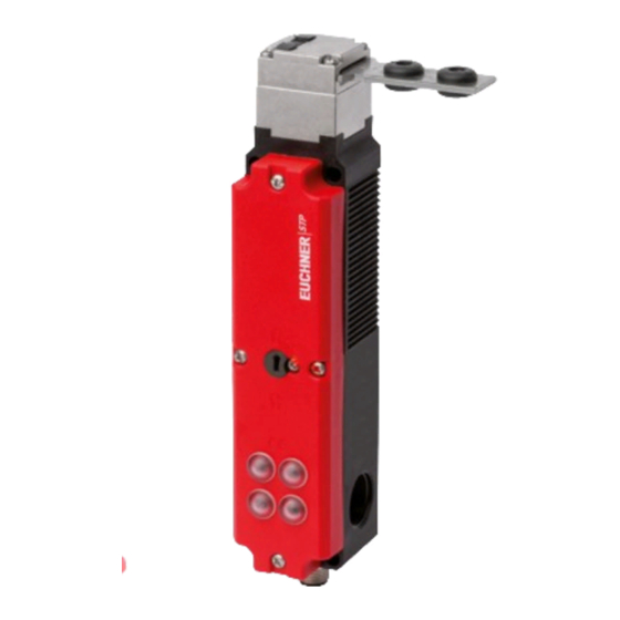
- Page 1 Operating Instructions Transponder-Coded Safety Switch With Guard Locking CTP-L.-AS1 Unicode/Multicode...
-
Page 2: Table Of Contents
Operating Instructions Transponder-Coded Safety Switch CTP-L.-AS1 Contents About this document ..................... 4 1.1. Scope ............................4 1.2. Target group ..........................4 1.3. Key to symbols ..........................4 1.4. Supplementary documents ......................4 Correct use ......................5 Description of the safety function ................6 Exclusion of liability and warranty ................. 7 General safety precautions ................... - Page 3 Operating Instructions Transponder-Coded Safety Switch CTP-L.-AS1 Setup ......................... 18 11.1. LED displays ..........................18 11.2. Teach-in function for actuator (only for unicode evaluation) ...............18 11.2.1. Actuator teach-in ......................18 11.3. Functional check ...........................19 11.3.1. Mechanical function test ....................19 11.3.2. Electrical function test ....................19 System status table ....................
-
Page 4: About This Document
Important! Always read all documents to gain a complete overview of safe installation, setup and use of the device. The documents can be downloaded from www.euchner.com. For this purpose enter the doc. no. in the search box. (translation of the original operating instructions) 2124662-03-05/18... -
Page 5: Correct Use
EN 60204-1, Safety of machinery – Electrical equipment of machines – Part 1: General requirements The safety switch is allowed to be operated only in conjunction with the intended EUCHNER actuator and the related connec- tion components from EUCHNER. On the use of different actuators or other connection components, EUCHNER provides no warranty for safe function. -
Page 6: Description Of The Safety Function
Operating Instructions Transponder-Coded Safety Switch CTP-L.-AS1 3. Description of the safety function Devices from this series feature the following safety functions: Monitoring of guard locking and the position of the guard (interlocking device with guard locking according to EN ISO 14119) Ì Safety function (see chapter 6.3. -
Page 7: Exclusion Of Liability And Warranty
Prior to use, read the operating instructions and keep these in a safe place. Ensure the operating instructions are always available during mounting, setup and servicing. EUCHNER cannot provide any warranty in relation to the readability of the CD for the storage period required. For this reason you should archive a printed copy of the operating instructions. -
Page 8: Function
Operating Instructions Transponder-Coded Safety Switch CTP-L.-AS1 6. Function The device permits the locking of movable guards. Transponder-coded actuator The system consists of the following components: coded actuator (transponder) and switch. Whether the device learns the complete actuator code (unicode) or not (multi- code) depends on the respective version. -
Page 9: Guard Locking On Version Ctp-L2
Operating Instructions Transponder-Coded Safety Switch CTP-L.-AS1 6.2. Guard locking on version CTP-L2 (Guard locking actuated by power-ON and released by spring force) Important! Use as guard locking for personnel protection is possible only in special cases, after strict assessment of the accident risk (see EN ISO 14119:2013, section 5.7.1)! Activating guard locking: Apply auxiliary power to the solenoid and set AS-Interface output bit D0. -
Page 10: Manual Release
Operating Instructions Transponder-Coded Safety Switch CTP-L.-AS1 7. Manual release Some situations require the guard locking to be released manually (e.g. malfunctions or an emergency). A function test should be performed after release. More information on this topic can be found in the standard EN ISO 14119:2013, section 5.7.5.1. The device can feature the following release functions: 7.1. -
Page 11: Emergency Unlocking (Can Be Retrofitted)
Operating Instructions Transponder-Coded Safety Switch CTP-L.-AS1 7.2. Emergency unlocking (can be retrofitted) Permits opening of a locked guard from outside the danger zone without tools. For mounting, see the mounting supplement. Important! Ì It must be possible to operate the emergency unlocking manually from outside the protected area without tools. -
Page 12: Actuating Escape Release
Operating Instructions Transponder-Coded Safety Switch CTP-L.-AS1 7.3.1. Actuating escape release Ì Press the red release knob to the end stop Guard locking is released. ¨ Pull the knob out again to reset. The half-sequence/zero sequence is sent via the ASi bus when the escape release is actuated. Open the guard and close it again after resetting the escape release. -
Page 13: Changing The Approach Direction
Operating Instructions Transponder-Coded Safety Switch CTP-L.-AS1 8. Changing the approach direction The approach direction needs to be changed only if the switch is to be approached from the rear. Proceed as follows: 1. Remove the screws from the safety switch 2. -
Page 14: Installation
Operating Instructions Transponder-Coded Safety Switch CTP-L.-AS1 9. Installation CAUTION Safety switches must not be bypassed (bridging of contacts), turned away, removed or otherwise rendered ineffective. Ì Observe EN ISO 14119:2013, section 7, for information about reducing the possibilities for by- passing an interlocking device. NOTICE Risk of damage to equipment and malfunctions as a result of incorrect installation. -
Page 15: Electrical Connection
Operating Instructions Transponder-Coded Safety Switch CTP-L.-AS1 10. Electrical connection View of safety switch plug connector 1 AS-Interface + 2 Auxiliary voltage 0 V 3 AS-Interface - 4 Auxiliary voltage 24 V Figure 3: Terminal assignment, AS-Interface M12 plug connector 10.1. Notes about Important! Ì... -
Page 16: Dual-Channel Conditionally Dependent
Cause: slave address = 0 red/green Device fault in the slave. alternately flashing Contact EUCHNER. red flashing 10.5. Safety in case of faults The ASi power supply and the auxiliary voltage are reverse polarity protected. (translation of the original operating instructions) 2124662-03-05/18... -
Page 17: Connection Of Guard Locking Control
Operating Instructions Transponder-Coded Safety Switch CTP-L.-AS1 10.6. Connection of guard locking control 10.6.1. Guard locking control by means of switching the auxiliary voltage Auxiliary voltage, 24 V DC Auxiliary voltage, 0 V DC Figure 4: Connection example guard locking control by means of switching the auxiliary voltage 10.6.2. -
Page 18: Setup
Operating Instructions Transponder-Coded Safety Switch CTP-L.-AS1 11. Setup 11.1. LED displays You will find a detailed description of the signal functions in chapter 12. System status table on page 20. Color green/red STATE green LOCK/DIA yellow/red STATE LOCK/DIA 11.2. Teach-in function for actuator (only for unicode evaluation) The actuator must be allocated to the safety switch using a teach-in function before the system forms a functional unit. -
Page 19: Functional Check
Operating Instructions Transponder-Coded Safety Switch CTP-L.-AS1 11.3. Functional check WARNING Danger of fatal injury as a result of faults in installation and functional check. Ì Before carrying out the functional check, make sure that there are no persons in the danger zone. Ì... -
Page 20: System Status Table
Operating Instructions Transponder-Coded Safety Switch CTP-L.-AS1 12. System status table The dual LOCK/DIA LED displays the colors red and yellow. Depending on the state, both colors can flash alternately. LED indicator Output Operating mode State closed Normal operation, door closed and locked 1 x ... -
Page 21: Technical Data
Operating Instructions Transponder-Coded Safety Switch CTP-L.-AS1 13. Technical data NOTICE If a data sheet is included with the product, the information on the data sheet applies. 13.1. Technical data for safety switch CTP-AS Parameter Value Unit min. typ. max. General Material - Switch head Die-cast zinc... -
Page 22: Dimension Drawing For Safety Switch Ctp
Operating Instructions Transponder-Coded Safety Switch CTP-L.-AS1 13.2. Dimension drawing for safety switch CTP… Version with plug connector M12 With escape release The actuator shaft for the escape release can be extended using exten- sions (max. 94 mm) Basic position for escape release ∅ 5.3 (4x) 44 / 74 / 94... - Page 23 Operating Instructions Transponder-Coded Safety Switch CTP-L.-AS1 With auxiliary key release With auxiliary release max. 50 With emergency unlocking With wire front release 21,5 32,4 2124662-03-05/18 (translation of the original operating instructions)
-
Page 24: Technical Data For Actuator Ctp
Operating Instructions Transponder-Coded Safety Switch CTP-L.-AS1 13.3. Technical data for actuator CTP-... Parameter Value Unit min. typ. max. Housing material Fiber reinforced plastic Weight 0.03 … 0.06 (depending on version) Ambient temperature °C Degree of protection IP 67/IP 69/IP 69K Mechanical life 1 x 10 Locking force, max. - Page 25 Operating Instructions Transponder-Coded Safety Switch CTP-L.-AS1 37,5 122667 A-C-H-W-SST-122667 12,45 A-A 1 : 2 37,2 122668 A-C-H-W-SST-122668 5,25 2124662-03-05/18 (translation of the original operating instructions)
- Page 26 Operating Instructions Transponder-Coded Safety Switch CTP-L.-AS1 Dimension drawing Min. door radius [mm] Order no./item 3,25 122671 A-C-H-RL-LS-122671 max. 28 X = 53 mm (122671, 122672) X = 49 mm (122669, 122670) 122672 A-C-H-RR-LS-122672 122675 A-C-H-RO-LS-122675 max. 28 X = 41 mm (122673, 122674) X = 45 mm (122675, 122676) 13,2 X = 41 mm (122673, 122674)
-
Page 27: Ordering Information And Accessories
14. Ordering information and accessories Tip! Suitable accessories, e.g. cables or assembly material, can be found at www.euchner.com. To order, enter the order number of your item in the search box and open the item view. Accessories that can be combined with the item are listed in “Accessories.”... -
Page 28: Declaration Of Conformity
Operating Instructions Transponder-Coded Safety Switch CTP-L.-AS1 17. Declaration of conformity (translation of the original operating instructions) 2124662-03-05/18... - Page 29 Operating Instructions Transponder-Coded Safety Switch CTP-L.-AS1 2124662-03-05/18 (translation of the original operating instructions)
- Page 30 Operating Instructions Transponder-Coded Safety Switch CTP-L.-AS1 (translation of the original operating instructions) 2124662-03-05/18...
- Page 31 Operating Instructions Transponder-Coded Safety Switch CTP-L.-AS1 2124662-03-05/18 (translation of the original operating instructions)
- Page 32 Edition: 2124662-03-05/18 Title: Operating Instructions Transponder-Coded Safety Switch CTP-L.-AS1 (translation of the original operating instructions) Copyright: © EUCHNER GmbH + Co. KG, 05/2018 Subject to technical modifications; no responsibility is accept- ed for the accuracy of this information.
Need help?
Do you have a question about the CTP-L.-AS1 Unicode and is the answer not in the manual?
Questions and answers