Rinnai Demand Duo R-Series Installation And Operation Manual
Hide thumbs
Also See for Demand Duo R-Series:
- Installation and operation manual (51 pages) ,
- Conversion manual (12 pages)
Table of Contents
Advertisement
Quick Links
Advertisement
Table of Contents

Related Manuals for Rinnai Demand Duo R-Series


Summary of Contents for Rinnai Demand Duo R-Series
- Page 2 WARNING IF THE INFORMATION IN THESE INSTRUCTIONS IS NOT FOLLOWED EXACTLY, A FIRE OR EXPLOSION MAY RESULT CAUSING PROPERTY DAMAGE, PERSONAL INJURY OR DEATH. — Do not store or use gasoline or other flammable vapors and liquids in the vicinity of this or any other appliance. —...
-
Page 3: Table Of Contents
1. Welcome ............................4 1.1 To the Installer ........................4 1.2 To the Owner ......................... 4 2. Safety ............................5 2.1 Safety Symbols ........................5 2.2 Safety Precautions ......................... 5 3. About the Water Heater ....................... 7 3.1 Components ........................... 7 3.2 Specifications ......................... -
Page 4: To The Owner
Thank you for purchasing Rinnai’s Demand Duo™ R-Series Commercial Automatic Circulating Tank Water Heater. This manual • You must read the entire manual to properly provides information on the installation, operation, operate the water heater and understand and maintenance of Rinnai’s Demand Duo™... - Page 5 − Turn off the gas at the gas valve, usually located immediately before the water heater. − Turn off the incoming water supply. This can be done at the isolation valve immediately before the water heater or by turning off the water supply to the building. •...
- Page 6 • Install the vacuum relief valve per local CAUTION codes. Massachusetts 248 CMR Section 10.14 (I) “All potable water pressure tanks • BURN HAZARD. Hot exhaust and vent may shall be provided with a vacuum relief valve cause serious burns. Keep away from the water heater unit.
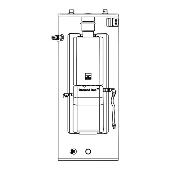
- Page 7 Figure 1 Intake Filter Exhaust Connector (IFEC) (Supplied installed) Electric Conduit Pump Upper Tank IMPORTANT Thermistor The tankless engine is to be used as a service part only for the Demand Duo™ R-Series System. RE is not permitted as a substitute. REC is not permitted as tankless only application.
- Page 8 Product Number CHS19980RECiN CHS19980RECiP Product Description Automatic Circulating Tank Water Heater Installation Type Indoor Minimum Gas Consumption Btu/hr (kW/hr) 11,900 (3.5) Maximum Gas Consumption Btu/hr (kW/hr) 199,000 (58.3) Tank Volume 80 Gallons (303 Liters) First Hour Delivery at 100°F Rise 249 Gallons (942 Liters) Temperature Setting 120°F (49°C) to 180°F (82°C)
- Page 9 Product Number CHS199100RECiN CHS199100RECiP Product Description Automatic Circulating Tank Water Heater Installation Type Indoor Minimum Gas Consumption Btu/hr (kW/hr) 11,900 (3.5) Maximum Gas Consumption Btu/hr (kW/hr) 199,000 (58.3) Tank Volume 119 Gallons (450 Liters) 276 Gallons (1046 Liters) First Hour Delivery at 100°F Rise Temperature Setting 120°F (49°C) to 180°F (82°C) Product Weight...
- Page 10 Figure 2 Models 27.7 [703] Measurements in drawing CHS19980RECiN ø 24.1 [612] are shown in inches [millimeters]. CHS19980RECiP [203] 30° 17.3 [439] Front Side Cold Inlet Hot Outlet 35.6 [904] 63.3 65.25 [1608] [1657] 54.3 61.9 [1379] [1572] 23.8 [605] 27.2 [691] 4.2 [107]...
- Page 11 Figure 3 Models CHS199100RECiN 31.5 [800] ø CHS199100RECiP 28.5 [724] 16 [406] Measurements in drawing are shown in inches [millimeters]. 30° 19.7 [500] Side Front Cold Inlet Hot Outlet 40.2 [1020] 69.4 [1763] 71.4 [1814] 68.0 [1727] 56.5 [1436] 30.0 33.4 [762] [848]...
-
Page 12: What You Will Need
• Combustion air provided to the appliance Topics in this section should not be taken from any area of the structure that may produce a negative • Installation Guidelines pressure (i.e. exhaust fans, powered • What You Will Need ventilation fans). •... - Page 13 Heater) respective installation sections of this manual. • B-Vent Offset Adapter This section provides information on the importance of water quality to the Rinnai • R-Series Commercial Automatic Circulating Tank Pipe Wrenches (2) Water Heater. The information is intended to •...
- Page 14 Scale build-up is caused by hard water and can Back be accelerated if the water heater is set at a high temperature. Rinnai offers Southeastern Filtration’s “ScaleCutter Water Conditioning System” that offers superior lime 0 in. scale prevention and corrosion control by feeding a Both blend of control compounds into the cold water supply.
- Page 15 3. Position straps around the Demand Duo tank per the requirements of California Office of the State Architect. DO NOT POSITION 1. Choose the right hand truck to support the STRAPS OVER PIPE, FITTINGS or WIRE. weight and size of the water heater. Refer to 4.
-
Page 16: Venting Requirements
MUST not be used on this • All horizontal vent runs to be sloped up away water heater. Rinnai accepts no liability for from this appliance a minimum of ¼ in. (6 mm) damage or injury if such devices are installed on per foot (21 mm per meter). - Page 17 • Existing gas vent or chimney is to be Figure 7 checked to ensure they meet clearances and local codes. Vent Pipe • This appliance can ONLY be connected (Min. 6 in. diameter) to a manufactured chimney or vent that complies with a recognized standard.
- Page 18 Length: A vent connector shall be as short as practical Vent dampers must be certified in accordance and the appliance located as close as practical to with ANSI Z21.68 the chimney or vent. The maximum horizontal Before installing any flue damper, consult the length of the vent connector cannot exceed 75% local gas authority and damper manufacturer for of the height of the chimney or vent.
- Page 19 All gas vents shall extend through the roof flashing, roof jack, or roof thimble and terminate All flue (vent) gases must be directed to the with a listed cap or listed roof assembly. outdoors of the building or structure and must not The gas vent shall terminate at least 3 ft.
- Page 20 Common venting of this Category 1, fan-assisted Masonry Chimneys shall be built and installed in appliance is permitted. Consult the latest version accordance with NFPA 211, Standard for of the National Fuel Gas Code (ANSI Z223.1/ Chimneys, Fireplaces, Vents and Solid Fuel- NFPA 54).
- Page 21 Figure 10 32 ft. (9.7 m) This water heater requires adequate combustion air for ventilation and dilution of flue gases. Failure to provide adequate combustion air can result in unit failure, fire, explosion, serious bodily 32 ft. injury or death. Use the following methods to (9.7 m) ensure adequate combustion air is available for correct and safe operation of this water heater.
- Page 22 Figure 11 (Small Room, Closet, Alcove, Utility Room, Etc.) A confined space is defined in the National Fuel Gas Code, ANSI Z223.1/NFPA 54, and/or CSA B149.1 as "a space whose volume is less than 50 cubic feet per 1000 Btu/hr (4.8 m3 per kW per hour) of the aggregate input rating of all appliances installed in that space."...
- Page 23 Figure 15 Outdoor air can be provided to a confined space through two permanent openings, one commencing within 12 in. (300mm) of the top and one commencing within 12 in. (300mm) of the bottom, of the confined space. The openings shall communicate to the outside by one of two ways: 1.
- Page 24 □ Verify proper clearances around the vents. Ensure that the Combustion Air Requirements are followed that will provide sufficient combustion air □ for the appliance. Ensure you have used the correct venting products for Category 1 and that you have completely followed the venting manufacturer’s installation instructions and these installation instructions.
-
Page 25: Connect The Gas Supply
Topics in this section MUST DO • Connect the Gas Supply • A gas valve must be placed in the gas supply • Gas Operating Instructions line to the water heater. Flex line provided with • Gas Pipe Sizing Reference Tables the appliance can be used as a union. - Page 26 3. Thread the flare side of the 36 in. Gas Flex into the flare side of the Gas Flare Adapter (Figure 20). 1. Apply a pipe sealant approved for gas to the field-supplied 3/4 MNPT gas line Figure 20 (Figure 18). Flare Side NOTE 36 in.
-
Page 27: Instructions
FOR YOUR SAFETY READ BEFORE OPERATING If you do not follow these instructions exactly, a fire or explosion may WARNING result causing property damage, personal injury, or loss of life. A. This appliance does not have a pilot. It is •... - Page 28 The gas supply must be capable of handling the Table 7: Pipe Sizing Table - Natural Gas entire gas load required at the location. Gas line Pipe Sizing Table - Natural Gas sizing is based on gas type, the pressure drop in the system, the gas pressure supplied, and Schedule 40 Metallic Pipe gas line type.
- Page 29 WARNING • DO NOT use an extension cord or adapter plug with this appliance. • The water heater must be electrically grounded in accordance with local codes and ordinances or, in the absence of local codes, in accordance with the National Electrical Code, ANSI/NFPA No. 70. •...
- Page 30 5. Strip the green, white, and black field supplied wires 1/2 in. Make sure the conductors are completely bare (Figure 25). Figure 25 A manual gas control valve is placed in the □ gas line to the water heater. Check the gas lines and connections for □...
- Page 31 WARNING DO NOT adjust parameter settings unless specifically instructed to do so. To adjust the parameters: 1. Locate the PC Board (lower right side of unit). 2. Locate the two push buttons (A and B) on the PC Board. 3. Press the "A" button for 1 second. 4.
-
Page 32: Service Indicator (Service Soon, Ss)
This water heater includes a service indicator (Service Soon, ). When selected in the parameter settings, an code will display on the controller indicating that it is time to flush and service the water heater. • Selection is installers preference based on water conditions or other factors that may influence the suggested interval of service. -
Page 33: Prv Requirements
• If a PRV discharges periodically, this may be Topics in this section due to thermal expansion in a closed water supply system. Contact the water supplier or • Pressure Relief Valve Requirements local plumbing inspector on how to correct this •... - Page 34 Figure 30 A Hot Water Outlet Labels: B Hot Water Outlet Valve C Temperature-Pressure Demand Duo Serial Relief Valve Number Label D Cold and Hot Unions Temperature & Pressure Relief E Cold Water Supply Valve Valve Label F Cold Water Supply Tank Serial Number Label G Thermal Expansion Tank...
- Page 35 Single Unit Circulation Note: Installation must conform to applicable codes and all requirements listed in this manual. Balancing valves, equivalent piping, pressure gauges, and temperature gauges are to be used as necessary to ensure proper flow between units. All components shall be selected for the pressure and temperature rating of the installation. Figure 31 Hot Water Supply Line Cold Inlet (Optional)
- Page 36 Demand Duo™ R-Series (REC) Installation and Operation Manual...
- Page 37 1. Ensure the drain valve located at the bottom of the tank is closed. 2. Open the nearest hot water fixture in the plumbing system. 3. Open the cold water supply valve to the water heater. 4. Keep the hot water fixture open until the tank is filled and constant flow is obtained at the Water connections to the water heater should fixture.
- Page 38 The water heater is not subject to corrosive compounds in the air. Corrosive fumes, sometimes found in hair/ nail salons, spas, or other industries exposed to toxic fumes, may be released through □ vents when not in operation. Chemicals that are corrosive in nature should not be stored or used near the water heater or vent termination.
-
Page 39: Safety Precautions
Topics in this section Rinnai offers a “Scale Control System” that provides superior lime scale prevention and • Safety Precautions corrosion control by feeding a blend of control compounds into the water supply. - Page 40 Figure 33 Display Increases hot water temperature Enables controller Turns the water heater when multiple on or off controllers are used Decreases hot water temperature A temperature lower than 120°F (49°C) can be obtained at the tap by mixing with cold water. To change the temperature scale from Celsius to Fahrenheit or vice versa, press and hold the “On/Off”...
- Page 41 3. Press the (Up ) or (Down) buttons to obtain the desired temperature setting. The temperature can only be changed when the “In Use” light is off. Figure 35 Water temperatures over DANGER 125°F (52°C) can cause severe burns or scalding resulting in death.
- Page 42 1. To lock the controller, press and hold down To eliminate the beeps when keys are pressed the “Priority” button. follow the steps below. 2. While holding down the “Priority” button, press the (Up) button until a beep is heard 1.
- Page 43 Storage Tank Topics in this section Drain water through the drain valve at least once a year. This will remove excess sediment from • Diagnostic Codes the bottom of the tank. This sediment, if allowed to accumulate, will reduce the efficiency and the life of the tank.
-
Page 44: Maintenance
Cleaning and Inspecting the Pressure Relief Valves (IFEC) Air Filter Operate the pressure relief valve manually once a year. In doing so, it will be necessary to take INSPECTION: precautions with regard to the discharge of • To maintain optimum performance, potentially scalding hot water under pressure. - Page 45 NOTE exchanger. Scale build-up will affect the performance of the water heater. Water should be treated. Rinnai 1. Turn power on at the controller. offers water conditioning solutions that provide 2. Disconnect electrical power from the source.
- Page 46 To Display Performance Data 1. Press and hold the (Down) button. 2. While holding the (Down) button for 2 seconds, press and hold the “On/Off” button (hold both buttons simultaneously) (Figure 43) 3. Use the (Up) and (Down) buttons to scroll to the desired information described in Table 11: Performance Data Table.
- Page 47 This water heater is designed to display diagnostic codes. If there is a potential operation concern, refer to the code and remedy in this section. To Display Diagnostic Information Figure 44 1. Turn off the water heater by pressing the “On/Off” button. 2.
- Page 48 Thermal Fuse Combustion Air Temperature Sensor • Check for restrictions in air flow around • Check for restrictions in air flow around unit and vent terminal. unit and vent terminal. • Check gas type of unit and ensure it • Check sensor wiring for damage. matches gas type being used.
- Page 49 Recirculation Low Flow Scale Build-up in Heat Exchanger (when checking maintenance code history, • Ensure the inlet water filter is clean and “00” is substituted for “LC”) free of debris. • LC0~LC9 indicates that there is scale • Ensure Parameter setting are correctly build up in the heat exchanger and that set for recirculation mode.
- Page 50 Rinnai’s sole discretion. The warranty claim for product parts and labor may be denied if a component or product returned to Rinnai is found to be free of defects in material or workmanship; damaged by improper installation, use or operation; or damaged during return shipping.
- Page 51 Limitation on Warranties No one is authorized to make any other warranties on behalf of Rinnai America Corporation. Except as expressly provided herein, there are no other warranties, expressed or implied, including, but not limited to warranties of merchantability or fitness for a particular purpose, which extend beyond the description...
Need help?
Do you have a question about the Demand Duo R-Series and is the answer not in the manual?
Questions and answers