Table of Contents
Advertisement
Quick Links
Advertisement
Table of Contents
Troubleshooting

Subscribe to Our Youtube Channel
Related Manuals for WaterLogic WL3 FX


Summary of Contents for WaterLogic WL3 FX
- Page 1 WL3 FX MANUAL Waterlogic Commercial Products, LLC 3175 Bass Pro Drive Grapevine, TX 76051 (800) 288-1891 www.waterlogicdealers.com Tech Portal Website: techportal.waterlogic.com Waterlogic International, LTD – Global Headquarters Grenfell Road, Maidenhead, Berkshire, SL6 1HN, United Kingdom...
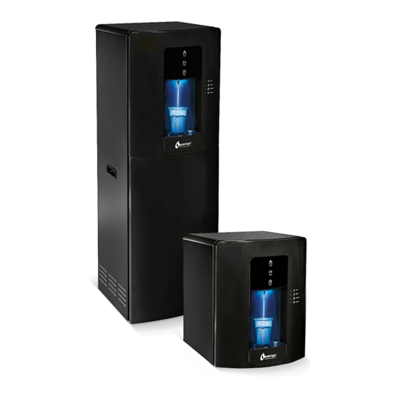
- Page 2 WL3 FX MANUAL Congratulations on your choice of the Waterlogic WL3 FX Water Treatment System. The WL3 FX model dispenses cold, ambient, and hot water. Every WL3 FX Water Treatment System includes: Bio-Cote Anti-Microbial Protection Firewall Advanced Purification Filter configuration can be optimized for all water conditions The Waterlogic WL3 FX Water Treatment System provides exceptional quality and great tasting water with every use.
-
Page 3: Table Of Contents
• Hot Tank Overheat (ROR) ............63 • Resetting the Hot Tank Overload ........... 64 • Power Troubleshooting............66 • Dispense Troubleshooting ............. 68 • Cold Water Troubleshooting ..........77 • Hot Water Troubleshooting ........... 78 WL3 FX Manual Page 3 - Revision: 7-27-2022... -
Page 4: Safety Alert Symbols
(RCD) having a rated residual operating current not exceeding 30mA. Use only Waterlogic supplied power cord. Never use extension cords or power strips to connect unit. Do not use if the power supply cord is damaged. Always unplug from power supply prior to servicing. - Page 5 WARNING! DO NOT OPERATE IF DAMAGED. Unplug and isolate water supply if abnormal conditions exist. Contact Waterlogic or authorized dealer for repair, service, and installation to avoid hazards. WARNING! HOT WATER. Unit produces Hot Water in excess of 80 C (175 F).
-
Page 6: Features And Benefits
OFF. When any one of the front buttons are pressed while the system is in energy saver mode, the WL3 FX will exit energy saver mode, and the hot tank will begin heating water. The hot water tank will be at set temperature within 10-minutes after exiting energy saver mode. -
Page 7: Certifications
CERTIFICATIONS WL3 FX Water Treatment Systems have been tested and certified to rigorous NSF and UL Standards. We believe that performance testing and certifications validate Waterlogic as a world-leader in water treatment systems. Waterlogic WL3 FX Component Certifications Include: UL399 – Certified Drinking Water Cooler Intertek Labs (ETL) Certified the WL3 FX Water Treatment System to ANSI/UL 399 Standard for Drinking Water Coolers. - Page 8 Energy Star Certified The WL3 FX Water Treatment System, has been tested and certified to the Energy Star, a US Environmental Protection Agency (EPA) program that helps our customers save money and protect our climate through superior energy efficiency.
-
Page 9: Model Designations And General Specifications
MODEL/PART DESIGNATIONS MODEL - BRAND NAME DESCRIPTION PART NUMBER WL3 FX Counter Top – Cold, Hot, Ambient WL3 FX Counter Top F-3FX-MU-HCA-TTL111NX-BL-WLU WL3FX-MU-HCA Serial Number Prefix: NB3H349BL WL3 FX Tower – Cold, Hot, Ambient WL3 FX Tower F-3FX-FS-HCA-TTL111NX-BL-WLU WL3FX-FS-HCA Serial Number Prefix: NB1H349BL... -
Page 10: Electrical And Shipping Specifications
15.2” ELECTRICAL SPECIFICATIONS ELECTRICAL SUPPLY 120V/60Hz, 1PH 15 Amp Service COMPONENT POWER (approximate) AMP DRAW (approximate) Heater 4.2 Amps Compressor 1.8 Amps UV Lamp System 0.15 Amps WL3 FX TOTAL 6.15 Amps WL3 FX Manual Page 10 - Revision: 7-27-2022... -
Page 11: Operating Instructions
OPERATING INSTRUCTIONS The above picture shows front user interface (UI) and control panel for the WL3 FX Water Treatment System. For Cold Water: Press and Hold the “Cold Dispense” Icon. For Hot Water: Press twice (within 3 seconds) and Hold the “Hot Dispense” Icon. LED will blink fast to indicate Hot Dispense is activated. -
Page 12: Warranty
(48) months from the date of manufacture. Waterlogic Commercial Products, LLC (“Waterlogic”) based in the U.S.A. and its affiliated companies are not liable for any cost of removal, installation, transportation, or any other charges which may arise in connection with a warranty claim. -
Page 13: Service Requirements
6. Clean and sanitize external surfaces of the WL3 FX Water Treatment System. Use soap and water or chemicals that are compatible with ABS plastic and will not damage or degrade the product surfaces. -
Page 14: Lg Compressor Description
External Capacitor LG CSB035LJCM 120V R134A 1/8HP Compressor Repair Parts Part # CO-0017-L00-00 LG Compressor 120V CSB035LJCM-PTC Relay Part # CO-0018-L00-00 LG Compressor 120V CSB035LJCM-Overload Protector Part # CO-0019-L00-00 LG Compressor 120V CSB035LJCM-Capacitor WL3 FX Manual Page 14 - Revision: 7-27-2022... -
Page 15: Hot Tank Principles Of Operation
HOT TANK PRINCIPLES OF OPERATION Vent Outlet Hot Tank Outlet To Faucet All Waterlogic Hot Tanks have a built in Vent or Expansion Chamber in the top of the tank except for WL270 (GF) units. Expansion Outlet Vent Chamber The Vent Chamber allows for expansion of the water when it is Hole heated. -
Page 16: Hot Tank Descaling
2. Connect descaling cartridge to the inlet water supply and connect to inlet bulkhead fitting on the back of the WL3 FX Water Treatment System. Turn on Water Supply. 3. Select Hot Water and depress the Main Dispensing Button on the Front Control Panel until descaling solution (colored water) comes out of the faucet. - Page 17 5. Allow descaling solution to remain in the Hot Tank for 15 minutes (length of time may vary depending on water conditions). 6. Place a pitcher, catch basin or other container under the faucet of the WL3 FX Water Treatment System.
-
Page 18: Replacement Components (Consumables)
FT-0053-IL-WLT CAUTION! Use only Waterlogic Replacement parts that can be obtained from Waterlogic or an Authorized Waterlogic Dealer, failure to do so will void the Warranty. See Installation and Service Manual for additional information. Hot Tank Service Hot Tanks (with controls) must be replaced at least every 3-5 years depending on usage. -
Page 19: Countertop Drawings And Parts List
WL3 FX COUNTER TOP DRAWING AND PARTS LIST Yellow = Consumables Green = Recommended spare parts Wetted Parts Drawing WL3 FX Manual Page 19 - Revision: 7-27-2022... - Page 20 Fuse Holder & Fuse 10-3014 EL-5053 110V/15A with only one wire chiller3 & Io Power Switch (Red)-No 12-5600 EL-5019-A back lights Switch - 10-3009 EL-5005 Heater/Compressor (Green) 19-1069 CT-2070-A Cold Tank Thermostat WL3 FX Manual Page 20 - Revision: 7-27-2022...
- Page 21 120V 60Hz v3 WL3 Countertop HCA ST-0064-L00-00 upper base panel PU-4008 PU-4008 JG Reducing Elbow 1/4" Firewall Assembly 14.1 CT-2078-B WL-4 Firewall UV Fixing WL Cube Spiral Quartz 14.2 FW-0008-L00-00 FW-0008-L00-00 Sleeve WL3 FX Manual Page 21 - Revision: 7-27-2022...
- Page 22 Bracket (mirror/no gauze) – India 14.6 AK-0064 UV Sensor With Wire 14.7 PL-1382 PL-1382 WL3 Hot Water Faucet JG Equal Tee Connector PU-4011 PU-4011 1/4" MS DC Solenoid Valve PU-0017-I00-00 PU-0017-I00-00 SWV24-01 WL3 FX Manual Page 22 - Revision: 7-27-2022...
- Page 23 SWV24-01 PU-4008 PU-4008 JG Equal Elbow 1/4" PU-4008 PU-4008 JG Equal Elbow 1/4" MS DC Solenoid Valve PU-0017-I00-00 PU-0017-I00-00 SWV24-01 PU-4011 PU-4011 JG Equal Tee 1/4" PU-4008 PU-4008 JG Equal Elbow 1/4" WL3 FX Manual Page 23 - Revision: 7-27-2022...
- Page 24 MS DC Solenoid Valve PU-0017-I00-00 PU-0017-I00-00 SWV24-01 PU-4008 PU-4008 JG Equal Elbow 1/4" 3min UV Timer PCB ST-8287 Fixing Bracket EN-0134-L00-00 WL3 NEW HCA MAIN PCB PU-4008 PU-4008 JG Equal Elbow 1/4" WL3 FX Manual Page 24 - Revision: 7-27-2022...
- Page 25 Unit Control Rubber Feet 10-3083 ST-8016 WL3000 WL3 Countertop Mini ST-0328-L00-00 Left Side Panel LG Compressor 120V CO-0020-L00-00 CO-0020-L00-00 R134A-CSB035LJCM Mini Down Base for 650 ST-8036 & Chiller white universal as ST-8012 WL3 FX Manual Page 25 - Revision: 7-27-2022...
- Page 26 WL3 HCA Countertop UI LP-0535-L00-00 Label WL3 Button Cover for PL-1379 LED Diffuser WL3 Countertop Front PL-0292-L00-BL Upper Panel - Black with FW Logo EN-6139 EN-6139 WL3 LED PCB EN-0135-L00-00 WL3 New HCA UI PCB WL3 FX Manual Page 26 - Revision: 7-27-2022...
- Page 27 Side Panel WL3 Countertop CO-0047-L00-00 Condenser JG Bulkhead Union PU-4028 PU-4028 1/4"x1/4" PU-4031 PU-4031 1/4" PE Pipe PU-4008 PU-4008 JG Equal Elbow 1/4" FT-0053 FT-0053 FT-0035 FT-0035 WL Inline Filter FT-0063 FT-0063 WL3 FX Manual Page 27 - Revision: 7-27-2022...
- Page 28 PU-0017-I00-00 SWV24-01 PU-4008 PU-4008 JG Equal Elbow 1/4" PU-4031 PU-4031 1/4" PE Pipe PU-4011 PU-4011 JG Equal Tee 1/4" MS DC Solenoid Valve PU-0017-I00-00 PU-0017-I00-00 SWV24-01 PU-4008 PU-4008 JG Equal Elbow 1/4" WL3 FX Manual Page 28 - Revision: 7-27-2022...
- Page 29 JG Equal Tee 1/4" PU-4031 PU-4031 1/4" PE Pipe PU-4008 PU-4008 JG Equal Elbow 1/4" Firewall Assembly PU-4031 PU-4031 1/4" PE Pipe PU-4011 PU-4011 JG Equal Tee 1/4" MS DC Solenoid Valve PU-0017-I00-00 PU-0017-I00-00 SWV24-01 WL3 FX Manual Page 29 - Revision: 7-27-2022...
- Page 30 No UV holder, No sub- tank)- FW JG Equal Straight PU-4010 PU-4010 Connector 1/4” PU-4031 PU-4031 1/4" PE Pipe PU-4008 PU-4008 JG Equal Elbow 1/4" MS DC Solenoid Valve PU-0017-I00-00 PU-0017-I00-00 SWV24-01 WL3 FX Manual Page 30 - Revision: 7-27-2022...
- Page 31 1/4" JG LLDPE Tube - Blue PU-4014 PU-4014 10-4029 HT-3024 Hot Tank Silicone Pipe 5/16" Non- PL-4064-L00-00 PL-4064-L00-00 WRAS Silicone Pipe 5/16" Non- PL-4064-L00-00 PL-4064-L00-00 WRAS PL-1382 PL-1382 WL3 Hot Water Faucet WL3 FX Manual Page 31 - Revision: 7-27-2022...
-
Page 32: Tower Drawings And Parts List
WL3 FX TOWER DRAWING AND PARTS LIST Wetted Parts Drawing WL3 FX Manual Page 32 - Revision: 7-27-2022... - Page 33 Fuse Holder & Fuse 110V/15A with 10-3014 EL-5053 only one wire chiller3 & Io EL-0061-L00-00 EL-0061-L00-00 Socket for Plug Connection V0 class 12-1101 CT-2016 Cold Tank Thermostat WL950,650,750 Universal Left&Right 10-4002 ST-8225 Side panel Black WL3 FX Manual Page 33 - Revision: 7-27-2022...
- Page 34 CO-0020-L00-00 CO-0020-L00-00 CSB035LJCM Down Base White - WL650 universal 12-1602 ST-8035 as ST-8011 PU-4008 PU-4008 JG Equal Elbow 1/4" PU-0017-I00-00 PU-0017-I00-00 MS DC Solenoid Valve SWV24-01 PU-4008 PU-4008 JG Equal Elbow 1/4" WL3 FX Manual Page 34 - Revision: 7-27-2022...
- Page 35 JG Equal Tee 1/4" PU-4011 PU-4011 JG Equal Tee 1/4" PU-0017-I00-00 PU-0017-I00-00 MS DC Solenoid Valve SWV24-01 PU-4008 PU-4008 JG Equal Elbow 1/4" CU-0001 CU-0001 Cushion for solenoid valve PU-4008 PU-4008 JG Equal Elbow 1/4" WL3 FX Manual Page 35 - Revision: 7-27-2022...
- Page 36 WL3 front down panel Black-No logo PL-0020-L00-BL PL-0020-L00-BL printing PL-0049-L00-BL- WL3 lower drip tray body for WLG black - WL logo - w.BioCote WL3 Drip tray grill - Black-Biocote PL-0029-L00-BL PL-0029-L00-BL added. WL3 FX Manual Page 36 - Revision: 7-27-2022...
- Page 37 PL-0017-L00-BL PL-0017-L00-BL Logo EN-6139 EN-6139 WL3 LED PCB EN-0135-L00-00 WL3 NEW HCA UI PCB ST-0331-L00-00 WL3 HCA UI PCB Cover 10-3083 ST-8016 Unit Control Rubber Feet WL3000 10-4004 PL-1120 Plastic Handle Black WL3 FX Manual Page 37 - Revision: 7-27-2022...
- Page 38 Drain Hole EL-0016-L00 EL-0016-L00-00 Power Transformer 120V/2A 13W/15W Electronic Ballast 120V EN-0008-LA1-00 EN-0008-LA1-00 60Hz PU-4008 PU-4008 JG Equal Elbow 1/4" PL-1382 PL-1382 Hot Faucet Firewall Assy 47.1 CT-2078-B WL-4 Firewall UV Fixing WL3 FX Manual Page 38 - Revision: 7-27-2022...
- Page 39 (Mirror/No Gauze) with Bracket IND 47.6 AK-0064 UV Sensor with Wire 47.7 FW-0046-L00-00 WL4 Firewall – AL Faucet Bracket UV Cold Tank Assy 4L – No UV CT-2017-A CT-2017-A Holder, no sub-tank) - FW WL3 FX Manual Page 39 - Revision: 7-27-2022...
- Page 40 3minutes UV Timer PCB Fixing ST-8287 Bracket EN-0134-L00-00 WL3 NEW HCA MAIN PCB PU-4011 PU-4011 JG Equal Tee 1/4" PU-0017-I00-00 PU-0017-I00-00 MS DC Solenoid Valve SWV24-01 PU-4008 PU-4008 JG Equal Elbow 1/4" WL3 FX Manual Page 40 - Revision: 7-27-2022...
- Page 41 JG Equal Elbow 1/4" FT-0053 FT-0053 FT-0035 FT-0035 WL Inline Filter FT-0063 FT-0063 PU-4008 PU-4008 JG Equal Elbow 1/4" PU-4008 PU-4008 JG Equal Elbow 1/4" PU-0017-I00-00 PU-0017-I00-00 MS DC Solenoid Valve SWV24-01 WL3 FX Manual Page 41 - Revision: 7-27-2022...
- Page 42 JG Equal Tee 1/4" PU-0017-I00-00 PU-0017-I00-00 MS DC Solenoid Valve SWV24-01 PU-4008 PU-4008 JG Equal Elbow 1/4" PU-4031 PU-4031 1/4" PE Pipe PU-4011 PU-4011 JG Equal Tee 1/4" PU-4031 PU-4031 1/4" PE Pipe WL3 FX Manual Page 42 - Revision: 7-27-2022...
- Page 43 1/4" PE Pipe PU-4011 PU-4011 JG Equal Tee 1/4" PU-0017-I00-00 PU-0017-I00-00 MS DC Solenoid Valve SWV24-01 PU-4008 PU-4008 JG Equal Elbow 1/4" PU-4031 PU-4031 1/4" PE Pipe PU-4008 PU-4008 JG Equal Elbow 1/4" WL3 FX Manual Page 43 - Revision: 7-27-2022...
- Page 44 JG Equal Elbow 1/4" PU-0017-I00-00 PU-0017-I00-00 MS DC Solenoid Valve SWV24-01 PU-0017-I00-00 PU-0017-I00-00 MS DC Solenoid Valve SWV24-01 PU-4007 PU-4007 JG Reducing Elbow 5/16-1/4" PU-4014 PU-4014 JG LLDPE Tube - Blue 8mm WL3 FX Manual Page 44 - Revision: 7-27-2022...
- Page 45 10-4029 HT-3024 Hot Tank PL-4064-L00-00 PL-4064-L00-00 Silicone Pipe 5/16" Non-WRAS PL-4064-L00-00 PL-4064-L00-00 Silicone Pipe 5/16" Non-WRAS PL-1382 PL-1382 WL3 Hot Water Faucet WL3 FX Manual Page 45 - Revision: 7-27-2022...
-
Page 46: Counter Top Flow Diagram
WL3 FX COUNTER TOP WATER FLOW DIAGRAM WL3 FX Manual Page 46 - Revision: 7-27-2022... -
Page 47: Tower Flow Diagram
WL3 FX TOWER WATER FLOW DIAGRAM WL3 FX Manual Page 47 - Revision: 7-27-2022... -
Page 48: Adjusting Cold Water Set Point
Turning the adjustment screw clockwise to lower the set point temperature. Do not adjust past the “Max Cold” position at 3:00 position to avoid freezing the cold tank. Turning the adjustment screw counter-clockwise to raise the set point temperature. WL3 FX Manual Page 48 - Revision: 7-27-2022... -
Page 49: Electrical Schematic
WL3 FX ELECTRICAL DIAGRAM DANGER! HIGH VOLTAGE ELECTRICAL HAZARD. PCB (Printed Circuit Board) contains High Voltage. Only trained and qualified technicians should attempt live testing. WL3 FX Manual Page 49 - Revision: 7-27-2022... - Page 50 WL3 FX ELECTRICAL DIAGRAM - SUPPLEMENT WL3 FX Manual Page 50 - Revision: 7-27-2022...
-
Page 51: Pre-Installation Procedures
Only qualified personnel who have read and understand this entire manual should attempt to install, or service this WL3 FX Water Treatment System, failure to do so could result in death or serious injury. DO NOT plug into an electrical supply until specifically instructed. - Page 52 Do not plug in unit unless qualified. Only qualified personnel who have read and understand this entire manual should attempt to install or service this unit. CAUTION! NEVER TURN ON HEATER BEFORE FILLING HOT TANK. WL3 FX Manual Page 52 - Revision: 7-27-2022...
- Page 53 The first 2 or 3 gallons of water will contain concentrated sanitizer. Use extreme care! Flushing the Sanitizer from the Machine 9. Place a pitcher, catch basin, or other container under the faucet of the WL3 FX Water Treatment System.
- Page 54 (high limit) will open and require manual reset. If the wire condenser at back of the WL3 FX Water Treatment System is warm, the refrigeration system is working.
-
Page 55: Countertop Draining Procedure
Turn off Water Supply and Bleed Water Pressure 3. Isolate the WL3 FX Water Treatment System from feed water by turning off the supply. 4. Dispense cold still water to relieve any pressure built up in the system. -
Page 56: Tower Draining Procedure
Switch (O=OFF), and dispense 2 liters of hot water from the machine. As hot water is dispensed from the faucet of the WL3 FX Water Treatment System, colder water will be introduced into the hot tank. Since the Red Heater and Compressor Power Switch is turned off, the heater will not energize and heat the incoming tap water. -
Page 57: Installation Instructions
WARNING! USE ONLY Waterlogic SUPPLIED POWER CORD. Locate system within 5 feet of power supply. Never use an extension cord or adapter. Do not use a damaged power cord or plug. Keep power cord out of heavy traffic areas and away from heat sources. Do not, under any circumstances, remove ground prong or alter the power cord. - Page 58 Pre-installation and sanitization procedures as prescribed in this manual must be performed before installing the WL3 FX Water Treatment System. Always install indoors and place the Waterlogic WL3 FX Water Treatment System on a firm, flat and stable surface. 1. Attach the water supply line to the 1/4” feed water inlet bulkhead fitting on the back of the WL3 FX Water Treatment System.
- Page 59 11. When the WL3 FX Water Treatment System has reached its Hot Temp Set Point, the heater will cycle off. When the WL3 FX Water Treatment System has reached its Cold Temp Set Point Temperature, the compressor will cycle off.
-
Page 60: Fault Code
ON. If no buttons are pressed on the front panel for 3 hours, the WL3 FX will enter sleep mode, and power to the heater will be shut down. The cold water (compressor) will remain active/on 24/7. -
Page 61: Disabling Energy Saving Mode
To DISABLE the energy saver, DIP #2 must be switched from ON to OFF (Down position), as per the legend printed on the board. This will enable the hot tank to cycle continuously. All units come with Sleep Mode enabled. WL3 FX Manual Page 61 - Revision: 7-27-2022... -
Page 62: Resetting The Filter Timer
RESETTING THE FILTER TIMER If the WL3 FX Water Treatment System has the Filter Timer dipswitches set to 3, 6, or 12 months, and the selected period has passed, the Filtration LED will begin blinking. This warning indicates that the filters need to be changed, and will continue until the timer has been reset, OR the Filter Timer has been set to “NONE.”... -
Page 63: Hot Tank Overheat (Ror)
HOT TANK OVERHEAT (ROR PROTOCOL TRIGGERED) The WL3 FX Water Treatment System has an ROR (Rate of Rise) protocol in the programming that will disable the hot tank and give audible and visual alarms if the temperature in the Hot Tank rises too rapidly, which usually indicates dry heating. -
Page 64: Resetting The Hot Tank Overload
RESETTING THE HOT TANK OVERLOAD The WL3 FX Water Treatment System has a Hot Tank equipped with a High Limit or Overload Thermostat. This is to prevent damage to the unit if the temperature in the Hot Tank gets too high. If the temp does get out of control, this Overload Thermostat will break the electric connection, cutting power from the heating element. - Page 65 Locate the Overload Thermostat on the front of the Hot Tank (has a bright red button on it). Reach in and depress the red button in the center of the thermostat to manually reset the Overload Thermostat. CLOSE UP OF THE MANUAL OVERLOAD WL3 FX Manual Page 65 - Revision: 7-27-2022...
-
Page 66: Power Troubleshooting
Bad Transformer Replace Transformer Black Power Connector to the Properly connect. PCB is not properly connected Bad Front PCB Replace Front PCB - P/N EN-0135-L00-00 Defective Red Power Switch Replace Red Power Switch WL3 FX Manual Page 66 - Revision: 7-27-2022... - Page 67 5. Red Power Switch is lit, but Green Power LED is not lit Possible Reason Solution Press any Dispense Button to wake the machine. Power LED should Machine is in Sleep Mode become lit and Hot Tank will begin heating again. WL3 FX Manual Page 67 - Revision: 7-27-2022...
-
Page 68: Dispense Troubleshooting
13. Cold Water dispenses from Faucet and Vent Outlet Simultaneously 14. Dispense Buttons stick 15. Run-On Water continues to dispense out of faucet after releasing the dispense button Also includes related instruction for Hot Tank Descaling WL3 FX Manual Page 68 - Revision: 7-27-2022... - Page 69 Check water pressure at the inlet bulkhead with a water pressure Recommend 40-60 psi for the gauge. Additional method of verification is to turn off water to unit WL3 FX Water Treatment and press the dispense button. Does the solenoid open without System to operate properly.
- Page 70 Additional method of verification is to turn off water to unit Recommend 40 to 60 psi for and press the dispense button. Does the solenoid open WL3 FX Water Treatment without water pressure to the unit? Listen for solenoid to System to operate properly.
- Page 71 Hot Descale the Tank. Tank vent chamber which See Hot Tank Descaling Instructions that are included further blocks the normal path of below win this Troubleshoot Section. water to expand. WL3 FX Manual Page 71 - Revision: 7-27-2022...
- Page 72 See Hot Tank Descaling Instructions that are included further Hot Tank outlet hole is scaled below in this Troubleshooting Section. over. See instructional video on the Partner Area of the Waterlogic.com website for more information. Expansion chamber is not Replace the Hot Tank.
- Page 73 Vent Outlet Hot Tank Outlet To Faucet All Waterlogic Hot Tanks have a built in Vent or Expansion Chamber in the top of the tank except for WL270 (GF) units. The Vent Chamber allows for expansion of the water when it Expansion is heated.
- Page 74 Additional method of verification is to turn off water to unit Recommend 40 to 60 psi for and press the dispense button. Does the solenoid open WL3 FX Water Treatment without water pressure to the unit? Listen for solenoid to System to operate properly.
- Page 75 Additional method of verification is to turn off water to unit Recommend 40 to 60 psi for and press the dispense button. Does the solenoid open WL3 FX Water Treatment without water pressure to the unit? Listen for solenoid to System to operate properly.
- Page 76 15. Run On – Water continues to dispense out of faucet after releasing the dispense button Reason “Run On” or “Carry On” is present in all Waterlogic pressure fed units without outlet solenoids. “Run On” is defined is the amount of water that continues to dispense out of the faucet after releasing the dispense button.
-
Page 77: Cold Water Troubleshooting
Wait for cold tank to chill water to temperature prior to dispensing more cold water. Cold tank capacity is 4 liters for Tower and 2 liters for Counter A greater capacity of Waterlogic Water Systems is available. Top. Check continuity of thermostat with multimeter. Replace Cold Water Thermostat thermostat as required. -
Page 78: Hot Water Troubleshooting
Visually inspect wire leads gong to the hot tank; confirm connected wire(s) to the proper connections to the heating elements. Heating Element / Hot Tank. Hot tank life is 3-5 years, depending on usage. WL3 FX Manual Page 78 - Revision: 7-27-2022... - Page 79 Attempt to dispense water from the hot tank. Once water flows, turn the green switch back on. Overload will “click” when pushed. The overload is Hot Tank Overload Tripped automatically reset when pressed. WL3 FX Manual Page 79 - Revision: 7-27-2022...
Need help?
Do you have a question about the WL3 FX and is the answer not in the manual?
Questions and answers