Table of Contents
Advertisement
Quick Links
Advertisement
Table of Contents

Related Manuals for jbc ALE-908UVA


Summary of Contents for jbc ALE-908UVA
- Page 1 INSTRUCTION MANUAL Automatic-Feed Soldering Control Unit...
-
Page 2: Packing List
This manual corresponds to the following references: With Solder Wire Perforation Without Solder Wire Perforation: for wire ø 0.8mm: for wire ø 0.4mm: - ALE-908UVA (100V) - ALE-204UA (230V) - ALE-108UVA (120V) for wire ø 0.5mm: - ALE-208UVA (230V) - ALE-205UA (230V) for wire ø... - Page 3 The following items are included according purchased reference: Components already Components already assembled in assembled in Control Unit Control Unit Solder Wire Guide Kit ..........................1 unit With solder wire perforation: Without solder wire perforation: for wire Ø 0.8 mm / Ø 0.032 in for wire Ø...
-
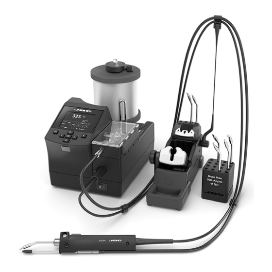
Page 4: Features And Connections
Features and Connections ALE250 Automatic-Feed Soldering Iron* Solder Reel Stand Automatic-Feed Soldering Control Unit Control Screen SOLDER WIRE USB-A GUIDE Connector Kit for ALE250 availabe for different solder wire diameters see page 11 + 12 Main Switch Peripherials RJ12 Connection for Robot System ALES Stand for ALE250... - Page 5 Solder Reel Assembly Reel Locking Axis Reel Locking Screw Solder Reel Solder Wire Guidedance Solder Wire Open the reel locking screw (1) and remove the reel locking (2) from the axis. Mode Con�nuous Tin reload process Mode Speed 20.0mm/s Place the �n on the gears Con�nuous and press: Feeder parameters lock...
-
Page 6: Tool Assembly
Press ok to exit Edit program Edit program Mode Program Sta�on se�ngs Edit program Edit program English Speed Speed Set default programs Mode Con�nuous Mode Con�nuous Feeder se�ngs Deutsch Sta�on se�ngs Off Feeder parameters lock 20.0mm/s Speed 20.0mm/s Speed Tool se�ngs Speed Speed Tool Assembly... -
Page 7: Main Menu Screen
Main Menu Screen Acces to Main Menu by , select “Feeder Settings” (1) and then “Wire Diameter” (2) to adjust the value to the current solder wire diameter. Tin Reloaded Process Screen Select “Tin Reloaded Process” (1) and then use to feed the solder wire and advance until it comes out through the outlet nozzle. -
Page 8: Control Process
Control Process Feeder Setting Modes Choose between “continuous”, “discontinuous” and “program” mode. Access to Main Menu by select “Feeder Settings” and then “Mode”. Depending on the selected mode, different parameters are available for setup. Continuous Mode Discontinuous Mode Program Mode Troubleshooting Station troubleshooting available on the product page at www.jbctools.com... -
Page 9: Program Mode
Control Process Program Mode Quick Access to Feeder Setting Modes The solder wire dispensing values can be directly set up from the work screen. Press to change the tool temperature value. When the main screen is displayed, by pressing button speed and length value can be set up. The following parameters can be changed according to the different dispensing modes: - Contiunous Mode: Speed - Discontinuous Mode: Speed and length... -
Page 10: Menu Screen
Language Control Process Menu Screen Default PIN: 0105 Station Settings choose between mm and inches Feeder Settings Tool Settings Counters Press enter when finished partial and total counters are shown... - Page 11 Mode Con�nuous Mode Con�nuous 20.0mm/s Speed 20.0mm/s Speed Changing Guide Kits Mode Con�nuous Mode Con�nuous Off 20.0mm/s Feeder parameters lock 20.0mm/s Feeder parameters lock Speed Off Speed Changing Wheels and Blade Tin reload process Off Feeder parameters lock Tin reload process Feeder parameters lock Off...
- Page 12 Accesories Various guide sets are available. Select the appropriate guide set depending on the solder wire diameter to be used. Solder Wire Guide Kits for ALE250 with Solder Wire Perforation...
- Page 13 Accesories Solder Wire Guide Kits for ALE250 without Solder Wire Perforation...
-
Page 14: Maintenance
USE ONLY WITH A 250 V FUSE EARTH FUSE F1.25 A EARTH FUSE F1.25 A - Replace any defective or damaged pieces. Only use original JBC spare parts. - Repairs should only be performed by a JBC authorized technical service. - Page 15 Safety It is imperative to follow safety guidelines to prevent electric shock, injury, fire or explosion. - Do not use the units for any purpose other than soldering or rework. Incorrect use may cause a fire. - The power cord must be plugged into approved bases. Be sure that it is properly grounded before use.
- Page 16 Notes...
- Page 17 Notes...
-
Page 18: Specifications
With Solder Wire Perforation for wire ø 0.8mm: Ref. ALE-908UVA - 100V 50/60Hz. Input fuse: T2A. Earthing Fuse: F 1.25A. Output: 23.5V Ref. ALE-108UVA - 120V 50/60Hz. Input fuse: T2A. Earthing Fuse: F 1.25A. Output: 23.5V Ref. ALE-208UVA - 230V 50/60Hz. Input fuse: T1A. Earthing Fuse: F 1.25A. Output: 23.5V for wire ø... - Page 19 Specifications - Solder Wire Diameter: According purchased reference - Max. Wire Length: 250 mm / 9.84 in (for discontinous + program mode) - Min. Wire Length: 0.5 mm / 0.02 in - Forward Speed Range 0.5 to 50 mm/s / 0.02 to 1.97 in/s - Speed of Backward Funktion 0.0 to 5.0 mm/s / 0.5 to 0.20 in/s - Number of Programs:...
- Page 20 In order for the warranty to be valid, equipment must be returned, postage paid, to the dealer where it was purchased. Get 1 extra year JBC warranty by registering here: https://www.jbctools.com/productregistration/ within 30 days of purchase. This product should not be thrown in the garbage.
Need help?
Do you have a question about the ALE-908UVA and is the answer not in the manual?
Questions and answers