jbc ALE Instruction Manual
Automatic-feed soldering control unit
Hide thumbs
Also See for ALE:
- Instruction manual (25 pages) ,
- Manual (13 pages) ,
- Programmer's manual (32 pages)
Table of Contents
Advertisement
Quick Links
Advertisement
Table of Contents

Related Manuals for jbc ALE


Summary of Contents for jbc ALE
- Page 1 INSTRUCTION MANUAL Automatic-Feed Soldering Control Unit...
-
Page 2: Packing List
Without Solder Wire Perforation: for wire ø 0.8mm: for wire Ø 0.38 - 0.4 mm - ALE-908UVA (100V) - ALE-904A (100 V) for wire ø 1.0mm: for wire Ø 0.45 - 0.56 mm - ALE-910UVA (100V) - ALE-905A (100 V) for wire Ø... - Page 3 - Ref. GALE10D-A Warning! For correct operation, the diameter of the chosen solder wire must match that of the guide kit and its components (wheels, clamps and nozzles) assembled in the ALE. Guide sets for different diameters are available at www.jbctools.com/solder-wire- guide-kit-product-2098.html...
-
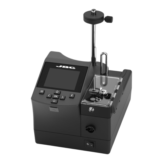
Page 4: Features And Connections
Features and Connections ALE250 Automatic-Feed Soldering Iron* Solder Reel Stand Automatic-Feed Soldering Control Unit Screen SOLDER WIRE USB-A GUIDE Connector Kit for ALE250 availabe for different solder wire diameters see page 11 + 12 Main Switch Peripherals Connector RJ12 Connector for FAE Robot System ALES Stand for ALE250... -
Page 5: Cartridge Assembly
para manuales - color gris 200 mm Cartridge Assembly 130 mm 130 mm For a safe cartridge assembly/change, make sure that the tool is unplugged and that any cartridge in place has cooled down before following these guidelines: AL250 Loosen the cartridge set screw (1), remove the used cartridge if there is any already in place, and insert the 100 mm new cartridge up to its mark (2). -
Page 6: Tool Assembly
25ºC Sel. temp. 325ºC Sel. temp. 325ºC Power Con�nuous Power Con�nuous Power Con�nuous Power Con�nuous Sel. temp. 325º Counters Backward None Backward Back Français 24.0 24.0 24.0 24.0 mm/s mm/s mm/s mm/s Tool se�ngs Reset Back Italiano Supplied: 12 mm Supplied: 12 mm Supplied: 12 mm Supplied: 12 mm... - Page 7 24.0 para manuales - color gris 200 mm mm/s Supplied: 12 mm º Ø 1.00 mm Sel. temp. 325ºC Upda�ng 1.00mm Your sta�ons is being updated 130 mm 130 mm Con�nuous Insert the solder reel in such a way - when viewed from above - that the solder wire unwinds on the 24.0 Do you want to update firmware? mm/s...
- Page 8 Mode Program Edit program Set default programs Feeder parameters lock Main Menu Screen Programs loaded Wire diameter 1.00mm Acces to Main Menu by pressing , select “Feeder settings” (1) and then “Wire diameter” (2) to Backward None adjust the value to the current solder wire diameter. 19:29 19:29 19:29...
- Page 9 para manuales - color gris 200 mm Solder Wire Feeding 130 mm 130 mm Forward the solder wire by pushing the dragging button (1) until the wire comes out of the tip (2). Solder Wire Dragging Button 100 mm 80 mm Alternatively, solder wire can also be fed using 19:29 19:29...
- Page 10 Inlet Nozzle 19:29 19:29 19:29 Tin reload process Mode Solder Wire Unloading ºC ºC ºC Place the �n on the gears Con�nuous and press: Discon�nuous Sel. Temp. Sel. Temp. Program 350ºC 350ºC Forward Power Discon�nuous Power Power Con�nuous Backward Back Without Solder Wire Perforation mm/s 10.0...
- Page 11 para manuales - color gris Off 200 mm Plug hrs mp level set 0min Working hrs eep delay 0min º Working hrs Sleep hrs eep temp º Sleep hrs 10min Hiber hrs Guide Kits Disassembly berna�on delay 10min Hiber hrs 130 mm 130 mm No tools hrs...
- Page 12 Sleep delay 0min Worki Sleep temp º Sleep Hiberna�on delay 10min Hiber Guide Kits Assembly - with Solder Wire Perforation: Peripher. No too Sleep Back Counter Assemble first the counter wheel (1). Make sure that its thread entry Wheel for the set screw is aligned with the flat side of the axis (2). If not, Fed cy the set screw will protrude, which may cause difficulties for the wire transportation.
- Page 13 Working hrs para manuales - color gris 200 mm eep hrs ber hrs o tools hrs Guide Kits Assembly - without Solder Wire Perforation: 130 mm 130 mm eep cyc Assemble first the counter wheel (1) in the same way as shown on the previous page (see (1), (2) and (3) on the page before).
-
Page 14: Control Process
Control Process Feeder Setting Modes Access to Main Menu by pressing , select “Feeder Settings” and then “Mode”. Choose between “continuous”, “discontinuous” and “program” mode. 19:29 Tin reload process Mode Tin reload process Con�nuous Tin reload process Mode Con�nuous Mode Tin reload process Speed 5.0mm/s... -
Page 15: Program Mode
Back Back Press ok to exit Press ok to exit Reset With ALE C.U. there can be up to 5 feeder programs defined. Select “Edit Program” and access the program parameters. 100 mm Tin reload process Tin reload p Edit program... -
Page 16: Menu Screen
Control Process Menu Screen Tin Reload Process Tin reload process Mode Con�nuous Tin reload process Mode Default PIN: 0105 Speed 5.0mm/s Feeder se�ngs Place the �n on the gears Con�n and press: Feeder parameters lock Discon Tool se�ngs Main Menu Tin reload process 1.00mm Wire diameter... - Page 17 Spring Ref. Solder Wire Ø range of use 0,8 mm GALE08V-A 0028358 0025270 0021696 0018632 0024955 0026693 0,032 in (Supplied 1,0 mm with ALE) GALE10V-A 0028359 0021560 0021699 0019170 0024956 0,040 in 0026695 0026696 1,2 mm GALE12V-A 0028360 0025272 0021158...
-
Page 18: Maintenance
EARTH FUSE F1.25 A EARTH FUSE F1.25 A EARTH FUSE F1.25 A EARTH FUSE F1.25 A - Replace any defective or damaged pieces. Use only original JBC spare parts. - Repairs should only be performed by a JBC authorized technical service. - Page 19 para manuales - color gris 200 mm Safety 130 mm 130 mm It is imperative to follow safety guidelines to prevent electric shock, injury, fire or explosion. 100 mm - Do not use the units for any purpose other than soldering or rework. Incorrect use may cause a fire. - The power cord must be plugged into approved bases.
- Page 20 Notes...
- Page 21 para manuales - color gris 200 mm Notes 130 mm 130 mm 100 mm 80 mm 60 mm 50 mm 40 mm...
- Page 22 Notes...
-
Page 23: Specifications
100 mm for wire ø 0.8mm: Ref. ALE-908UVA - 100V 50/60Hz. Input fuse: T2A. Earthing Fuse: F 1.25A. Output: 23.5V Ref. ALE-108UVA - 120V 50/60Hz. Input fuse: T2A. Earthing Fuse: F 1.25A. Output: 23.5V Ref. ALE-208UVA - 230V 50/60Hz. Input fuse: T1A. Earthing Fuse: F 1.25A. Output: 23.5V for wire ø... - Page 24 In order for the warranty to be valid, equipment must be returned, postage paid, to the dealer where it was purchased. Get 1 extra year JBC warranty by registering here: https://www.jbctools.com/productregistration/ within 30 days of purchase. This product should not be thrown in the garbage.
Need help?
Do you have a question about the ALE and is the answer not in the manual?
Questions and answers