
Subscribe to Our Youtube Channel
Related Manuals for ACTi A3 Series


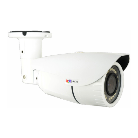
Summary of Contents for ACTi A3 Series
- Page 1 A3x, A4x Bullet Camera Hardware Manual A31, A41, A42, A43, A47, A49, A415 Ver. 2021/07/06...
-
Page 2: Table Of Contents
Connecting a Power Adapter (Optional) ........19 How to Connect Audio Input / Output Devices (Optional for A41~A47 only)............19 Connecting the Digital Input / Output Devices (Optional for A41~A47 only)............20 How to Connect DI/DO Devices ........... 20 www.acti.com... - Page 3 How to Insert the Memory Card ........... 21 How to Remove the Memory Card ..........21 How to Reset the Camera (A41~A47 only) ........22 Accessing the Camera Configure the IP Addresses ............23 Access the Camera ................. 27 www.acti.com...
-
Page 4: Precautions
Every reasonable care has been taken during the writing of this manual. Please inform your local office if you find any inaccuracies or omissions. We cannot be held responsible for any typographical or technical errors and reserve the right to make changes to the product and manuals without prior notice. www.acti.com... - Page 5 This product has been tested and found to comply with the limits for Class A Information Technology Equipment according to European Standard EN 55022 and EN 55024. In a domestic environment, this product may cause radio interference in which cause the user may be required to take adequate measures. www.acti.com...
-
Page 6: Safety Instructions
Safety Check Upon completion of any service or repairs to this video product, ask the service technician to perform safety checks to determine if the video product is in proper operating condition. www.acti.com... -
Page 7: Introduction
2MP, Zoom Bullet, Day / Night, Extreme WDR, Extreme Low Light Sensitivity, 4.3x Zoom Lens 3MP, Zoom Bullet, Day / Night, Extreme WDR, Superior Low Light Sensitivity, 4.3x Zoom Lens 3MP, Zoom Bullet, Day / Night, Adaptive IR, Extreme WDR, A415 Superior Low Light Sensitivity, 4.3x Zoom Lens www.acti.com... -
Page 8: Package Contents
Hardware Manual Package Contents Camera Mounting Screw Kit Camera Base Wrench Cable Gland with Washer DI/DO Terminal Block Drill Template (for A49 only) (A41~A47 only) Warranty Card Quick Installation Guide WARRANTY CARD www.acti.com... -
Page 9: Physical Description
Connecting a Power Adapter (Optional) page 19 for more information. Memory Card Slot Insert a memory card into the slot for local recording. See (A49 only) to Install / Remove the Memory Card (A49, A415 only) on page 21. www.acti.com... -
Page 10: A41, A42, A43, A47, A415
Digital Input / Output Devices (Optional for A41~A47 only) on page 20. Memory Card Slot Insert a memory card into the slot for local recording. See (A415 only) to Install / Remove the Memory Card (A49, A415 only) on page 21. www.acti.com... -
Page 11: Mounting Options
Suitable when mounting the camera on vertical poles. NOTE: For more information about the mounting solutions and accessories, please check the Mounting Accessory Selector in our website (http://www.acti.com/mountingselector). The above mounting accessories are not included in the package. Contact your sales agents to purchase. www.acti.com... -
Page 12: Installation Procedures
Cable hole If the cable will be routed along the wall, just drill the three (3) screw holes on the wall. 5. Detach the drill template sticker from the wall and insert the plastic plugs into the screw holes. www.acti.com... -
Page 13: Step 2: Mount The Camera
(3) holes and use the supplied screw tox. 2. Attach the camera to the surface using the three (3) supplied screws. 3. Adjust the camera installation angle and orientation, and then tighten the two (2) screws to fix its position. www.acti.com... -
Page 14: Step 3: Waterproof And Connect The Cable(S)
NOTES on using Ethernet cables: For outdoor installations, it is recommended to use exterior-grade Ethernet cables (CAT5/CAT5e/CAT6); ordinary Ethernet cables are only designed for indoor use and may deteriorate quickly when exposed to outdoor elements. Exterior-grade Ethernet cables are waterproof and do not require a conduit. www.acti.com... -
Page 15: Using The Cable Gland On A49
Perform the following to waterproof the “pigtail” using the cable gland: 1. Attach the washer to the Ethernet connector of the camera. 2. Detach the clamping nut and sealing insert from the gland body: Sealing Insert Clamping Nut Gland Body 3. Insert the clamping nut into the Ethernet cable. www.acti.com... - Page 16 Hardware Manual 4. Insert the sealing insert through the Ethernet cable. 5. Insert the cable through the gland body. 6. Push the sealing insert into the gland body. 7. Connect the RJ-45 connector to the camera connector. www.acti.com...
- Page 17 8. Attach the gland body to the camera connector. 9. Attach the clamping nut to the gland body to complete the cable solution. NOTE: Make sure the clamping nut is tightly attached to the cable gland body and the sealing insert is squeezed tightly. www.acti.com...
-
Page 18: Step 4: Connect To Network
Power Cable PoE Injector Ethernet Cable AC Power (Data + Power) Source Camera Step 6: Access the Camera Live View Accessing the Camera on page 23 for more information on how to access the Live View of the camera. www.acti.com... -
Page 19: Other Connections
Audio Output jack (GREEN) jack of the camera. Audio Output Jack Audio Device Audio Input Jack NOTE: Make sure that the connected audio input device has a built-in amplifier. Connecting an ordinary microphone will dwarf sounds and will result in inaudible recording. www.acti.com... -
Page 20: Connecting The Digital Input / Output Devices (Optional For A41~A47 Only)
Connect the wires of the input device to GND Digital Input (DI) and DI. NOTE: For more information on DI/DO connections, please refer to the Knowledge Base article All about Digital Input and Digital Output downloadable from the link below (http://www.acti.com/kb/detail.asp?KB_ID=KB20091230001). www.acti.com... -
Page 21: Other Adjustments And Accessories
In case there is a need to remove the card, make sure to access the camera Web Configurator to safely “unmount” the card first (see the camera Firmware manual for more information). Once unmounted from the firmware, push the card to eject it from the slot. www.acti.com... -
Page 22: How To Reset The Camera (A41~A47 Only)
1. Disconnect the camera from its power source (either by PoE or DC power). 2. Press and hold the Reset Button and re-connect the power source to the camera. 3. Continue pressing the Reset Button until the green Ethernet LED lights up or press for at least 20 seconds. www.acti.com... -
Page 23: Accessing The Camera
In the example below, we successfully found the camera model that had just connected to the network. Double-click the mouse button on the camera model name, the default browser of the PC is automatically launched and the IP address of the target camera is already filled in the address bar of the browser. www.acti.com... - Page 24 The latest IP Utility can be downloaded for free from http://www.acti.com/IP_Utility When you launch IP Utility, the list of connected cameras in the network will be shown. See sample illustration below: You can quickly notice the camera model in the list.
- Page 25 PC has to be configured to match the network segment of the camera. Manually adjust the IP address of the PC: In the following example, based on Windows 7, we will configure the IP address to 192.168.0.99 and set Subnet Mask to 255.255.255.0 by using the steps below: www.acti.com...
- Page 26 In such case, please plug in only one camera at a time, and change its IP address by using the Web browser before plugging in the next one. This way, the Web browser will not be confused about two devices having the same IP address at the same time. www.acti.com...
-
Page 27: Access The Camera
The examples in this manual are based on Internet Explorer browser in order to cover all functions of the camera. Assuming that the camera’s IP address is 192.168.0.100, you can access it by opening the Web browser and typing the following address into Web browser’s address bar: http://192.168.0.100 www.acti.com... - Page 28 Before logging in, you need to setup the root Account and Password of the camera. Then use this newly setup Account and Password to login to the Web Configurator. For further operations, please refer to the Firmware User Manual. www.acti.com...
- Page 29 Copyright © 2021, ACTi Corporation All Rights Reserved 7F, No. 1, Alley 20, Lane 407, Sec. 2, Ti-Ding Blvd., Neihu District, Taipei, Taiwan 114, R.O.C. TEL : +886-2-2656-2588 FAX : +886-2-2656-2599 Email: sales@acti.com...
Need help?
Do you have a question about the A3 Series and is the answer not in the manual?
Questions and answers