
Subscribe to Our Youtube Channel
Related Manuals for Godex BP2250i


Summary of Contents for Godex BP2250i
- Page 1 USER MANUAL BP2250i / BP2350i User Manual : BP2250i / BP2350i Version : Rev A Issue Date : 2015.01.22 : 920-016111-00...
- Page 2 61000- 4 Series EN 61000-3-2 / 2000 & EN 61000-3-3 / 1995. The equipment also tested and passed in accordance with the European Standard EN55022 for the both Radiated and Conducted emissions limits. BP2250i SERIES TO WHICH THIS DECLARATION RELATES IS IN CONFORMITY WITH THE FOLLOWING STANDARDS...
- Page 3 Printer Compliance Insert Note: This equipment may be used on an IT power system. For Users in English Speaking Regions (en) Caution: This marking indicates that the user should read all included documentation before use. The users of this product are cautioned to use accessories and peripherals approved by manufacturing company. The use of accessories other than those recommended, or changes to this product that are not approved by manufacturing company, may void the compliance of this product and may result in the loss of the user’s authority to operate the equipment.
- Page 4 Safety instructions Please read the following instructions carefully. Keep the equipment away from humidity. Before you connect the equipment to the power outlet, please check the voltage of the power source. Make sure the printer is off before plugging the power connector into the power jack.
-
Page 5: Table Of Contents
1. BOX CONTENT ................3 1.1 Box content ........................3 1-2. Specifications ........................ 3 1.3. Getting to know your printer ..................5 2. PRINTER SETUP ................7 2-1. Loading the label roll ....................7 2-2. Loading the ribbon ..................... 10 2-3. -
Page 6: Box Content
Empty ribbon core Quick Start guide CD (with GoLabel label software / user manual) 1-2. Specifications Model BP2250i BP2350i Print Method Thermal Transfer / Direct Thermal Resolution 203 dpi (8 dots/mm) 300 dpi (12 dots/mm) Print Speed... - Page 7 Model BP2250i BP2350i CODEPAGE 437, 850, 851, 852, 855, 857, 860, 861, 862, 863, 865, 866, 869, 737 Code Pages WINDOWS 1250, 1251, 1252, 1253, 1254, 1255, 1257 Unicode (UTF8, UTF16) Resident graphic file types are BMP and PCX, other graphic formats are downloadable...
-
Page 8: Getting To Know Your Printer
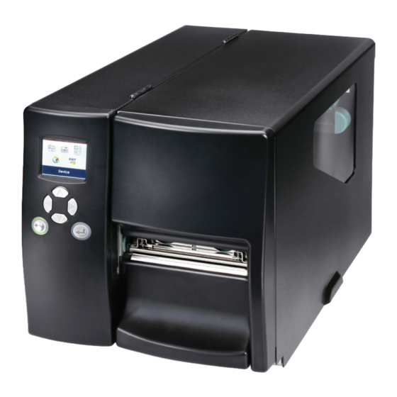
1.3. Getting to know your printer External view Operator panel Lower cover plate Viewing window Printer cover Feed slot for continuous labels Auto-Calibration button Parallel port (optional) Applicator interface (optional) USB Host Ethernet port USB port Serial port (DB-9) Power jack On/Off switch Feed slot for continuous labels... - Page 9 Internal view Ribbon rewind hub Ribbon supply hub Print mechanism Platen roller Tear-off plate Release lever for print head Adjustment wheel for sensor Paper guide Label tension guide Label supply hub Label roll guide Release catch Movable sensor...
-
Page 10: Printer Setup
. Printer setup This printer supports the following printing methods: Thermal transfer Requires a ribbon for transferring a printed image to a medium. printing (TTP) Direct thermal Does not require a ribbon, only thermal paper. printing (DTP) Please check which printing method you are using and alter the settings accordingly in the printer driver, printer menu, and/or software. - Page 11 Place the label roll on the label supply hub, pushing it right up to the printer housing. (Do not apply too much pressure to avoid damaging the label stock.) Fold the label roll guide back down and push it against the label roll.
- Page 12 The labels pass between the wall of the printer housing and the adjustable paper guide. 【 Note 】 Pass the labels through the printer as shown in the illustration. 10. Return the print head release lever to its original position. 11.
-
Page 13: Loading The Ribbon
2.2 Loading the ribbon 1. Place the printer on a flat surface and open the printer cover. 2. Pull out the print head release lever as shown in the illustration (1) and turn it anticlockwise to a top right position (2). -
Page 14: Connecting The Printer To The Host Computer
2.3 Connecting the printer to the host computer Please make sure that the printer is switched off. Connect the power cord to the AC adapter and connect the adapter to the printer. Connect the USB cable to the printer and host computer. Switch on the printer. -
Page 15: Installing Printer Driver And Golabel
Printer Setup 2.4 Intalling Printer Driver and GoLabel Installing Printer Driver Directly From CD Folder Insert the product CD in the CD/DVD drive of the host computer and open the "Seagull Drivers" folder on the C Select the icon for the driver file and click it to start the installation. Follow the instructions on the screen. - Page 16 Printer Setup Specify the port used to connect the printer to the host computer. Enter a printer name and assign the appropriate rights. BP EZ2250i BP EZ2250i Once the installation is complete, a summary of the printer settings is displayed. Check whether the printer settings are correct and click "Finish"...
- Page 17 Printer Setup Once the driver installation is complete, the new printer should appear in the "Printers and Faxes" folder. BP2250i BP2250i...
-
Page 18: Setting And Control For Operation Panel
Setting and Control for Operation Panel 3-1. Operation Panel Operation Panel Introduction LCD SCREEN OPERATION PANEL DIRECTION KEY FEED BUTTON POWER BUTTON POWER Button Press the POWER button to turn on the printer, and the START UP SCREEN appears. If the printer is on “ready to print”... -
Page 19: Lcd Interface Introduction
Setting and Control for Operation Panel LCD Interface Introduction Getting Started Press the POWER button to turn on the printer, and the START UP SCREEN appears. Power on If the printer is on “ready to print” status, the LCD screen should display the message “Ready“ on the screen. Please keep pressing ... - Page 20 Setting and Control for Operation Panel Operations on Setting Page On MAIN PAGE, press or button to move the cursor and select the functions. Select a designated function and press FEED button, you will enter the SETTING PAGES for the function. Select Enter On SETTING PAGES, press ...
- Page 21 Setting and Control for Operation Panel On SETTING VALUE PAGES, press or button to change the setting values. Select Press FEED button will apply the setting value you just selected, and the red tick will appear to mark the value. Apply **** The blue arrow indicates the value you are selected.
- Page 22 Setting and Control for Operation Panel Exit from Current Page to Ready Status The icon on top-left corner displays the capture of upper level screen and also guides you back to upper level with left or up arrow. NAVIGATION ICON On SETTING VALUE PAGES, press button will go back to the upper level screen.
- Page 23 Setting and Control for Operation Panel On MAIN PAGE, select the “EXIT” icon and press the FEED button to exit from SETTING MODE and the printer goes back to READY status. EXIT from Setting Mode Back to the Ready status...
-
Page 24: Lcd Interface Function
Setting and Control for Operation Panel LCD Interface Function Main Page Setting items for printer, ex. Printing speed, darkness. Also includes a Printing Wizard for your ease of printing. Printer Setting Setting items for printing label, ex. Rotation, Printing position offset. Label Setting Option modules and connection port settings. - Page 25 Setting and Control for Operation Panel Setting Items in Setting Mode English German LCD Language 繁體中文 简体中文 Printer Setting Speed 2-5 or 7 Darkness 0-19 Label with Gaps Media Type Label with Marks Wizard Continuous Direct Thermal Printer Mode Thermat Transfer Tear-off Position 0-40 Darkness...
- Page 26 Setting and Control for Operation Panel Apply Buzzer Cancel None Cutter Option Device Label Dispensor Optional Setting Applicator Apply Pre-Printing Cancel 4800 bps 9600 bps 19200 bps Baud Rate 38400 bps 57600 bps 115200 bps Serial Port Setting Parity Even 7 bits Data bits 8 bits...
- Page 27 Setting and Control for Operation Panel Status of LCD Interface When printer is on standby status (ready to print), the LCD interface will display “Ready” on screen. You can only print on this “Ready“ status. If there is any printers error, the LCD screen will display the error screen to show the type of error. You can fix the error according the notice.
-
Page 28: Label Calibration And Self Test
Turn the printer on again, keeping the FEED button pressed. The printer will now measure the label stock and store the label height. Once the printer has successfully measured the label stock, it will print a self-test label. The contents of a self-test printout are listed below. BP2250i:GX.XXX Model & Version USB S/N:12345678 USB ID setting... - Page 29 Setting and Control for Operation Panel Label Calibration Button A hardware button to make a Label Calibration while printer encountering ‘’Media Error’’ during the cases when first-time printer start up or change label or ribbon to another type, such as change using gap label to continuous or black mark labels.
-
Page 30: Error Alerts
Setting and Control for Operation Panel Error Alerts In the event of a problem that prevents normal functioning of the printer, you will see an error message on LCD screen and hear some beep signals. Please refer to below table for the error alerts. LCD 螢幕... - Page 31 Setting and Control for Operation Panel Operation Panel Status Type Beeps Description Solution The memory is full. The printer Delete unnecessary data or install prints the message "File System full additional memory. ". Use the "~X4" command to print Unable to find file. The printer all files.
-
Page 32: Usb Host
Setting and Control for Operation Panel 3.6 USB Host Definition : USB Host port supports either device:USB memory stick, keyboard or scanner. Purpose USB memory stick : It extends the user memory space up to 32GB for Graphic, Font, Label Format, DBF and Command ... - Page 33 Setting and Control for Operation Panel USB Keyboard When plug-in an USB keyboard to the printer, LCD panel will display “Standalone Mode”, press the “Enter” key on keyboard and “Feed” key in the printer to entering to the dialog for “Recall Label” operation. Only the sub-dialog “Recall Label”...
-
Page 34: Netsetting For Ethernet
4. NetSetting for Ethernet 4.1 Installing the NetSetting software The NetSetting software is used to manage the network configurations when connecting the printer via Ethernet port. It is available on product CD or can be downloaded from official website. To install the NetSetting, please follow below steps. -
Page 35: The Interface Of Netsetting
4. NetSetting for Ethernet 4.2 The Interface of NetSetting Click the NetSetting icon to start the program; you will see the start page as below. The start page will display the basic information of connected printer and your PC. Click the magnifier icon to search the printers which are connected via Ethernet port in you network environment. - Page 36 4. NetSetting for Ethernet IP Setting The IP Setting tab can change the printer name, Port number, Gateway setting and the password for configuring the printer. You can also set the printer’s IP address ether by DHCP or by Static IP. You can press “Set”...
- Page 37 4. NetSetting for Ethernet Alert Path Setting NetSetting will send the alert messages to designated mail account when the error happened on printer. The alert messages are sent by SMTP (Simple Mail Transfer Protocol) or SNMP (Simple Network Management Protocol). You can set or change the configurations of SMTP and SNMP on this “Alert Path Setting”...
- Page 38 NetSetting for Ethernet Alert Message Setting For the alert message notification function, you can decide which error cases need to be sent out to the operator. Moreover, the alert messages can be set to be sent by SMTP, SNMP or both. You can press “Set”...
- Page 39 Set or change the configurations of connected printer. Most of key settings for the printer operation can be done by this setting page. BP2250i You can press “Set” button to apply the settings and “ReGet” button to refresh the setting values.
- Page 40 NetSetting for Ethernet User Command The “User Command” tab provides a communication interface for operator to control the printer. Input printer commands in "Input Command" window and press “Send Command” button, the commands will be sent to the printer. For some commands that will return response message, the message will be displayed in "Output Message" window.
- Page 41 “Start Download Firmware” button. The printer firmware then can be updated remotely. BOOT : 1.000a1 F/W : BP2250i 1.000a In addition to the firmware update, you can press “Recover To Factory Settings” button to restore the printer configurations back to factory default.
-
Page 42: Accessories
. Accessories 5.1 Internal rewinder Rewinder Retention clip Screws (set of 4) Rewinder guide Note 【 】 Maximum height of the rewound medium: 118 mm 【 Suggestion 】 Medium thickness: 0.06 mm–0.25 mm Place the printer on a flat surface and open the printer cover. - Page 43 Remove the retention clip from the rewinder. Secure the rewinder on the printer housing using the four screws supplied. Now connect the rewinder cable to the printer housing. Installation of the rewinder module is now complete.
-
Page 44: Installing The Rewinder Guide
5.2 Installing the rewinder guide Unscrew the screw marked in the illustration on the front of the printer, which secures the lower cover plate. Remove the lower cover plate. 【 Note 】 Switch off the printer before starting the installation. Mount the rewinder guide on the print mechanism and secure it with screws. -
Page 45: Label Dispenser
5.3 Label dispenser Unscrew the screw marked in the illustration on the front of the printer, which secures the lower cover plate. Remove the lower cover plate. 【 Note 】 Switch off the printer before starting the installation. Place the printer the right way up again. - Page 46 Wind the label liner around the rewinder and secure it using the retention clip. Return the print head release lever to its original position. 【 Note 】 Please make sure that the label stock rewinds the right way onto the rewind hub. 10.
-
Page 47: Installing The Cutter
5.4 Installing the cutter Cutter cover Cutter module Cable clips Screws (set of 4) 【 Note 1 】 Remember to switch off the printer before installing the cutter. 【 Note 2 】 Do not use to cut adhesive labels! Glue residue will be left on the cutter blade and impair its functioning. - Page 48 Secure the cutter module on the printer housing using the screws. Connect the cutter cable connector to the cutter jack on the printer. Route the connection cable along the bottom of the printer housing using the cable clips. Place the cutter cover over the cutter module and secure it using the screw you removed from the lower...
-
Page 49: Installing The Parallel Adapter
5.5 Installing the Parallel adapter Parallel cable Parallel adapter Connection cable Screws (set of 2) Check whether the printer is switched off. Place the printer on a flat surface and open the printer cover. Unscrew the two screws marked in the illustration on the right and remove the left-hand side of the printer housing. - Page 50 Install the Parallel adapter in its place and secure it on the housing with screws. Connect the 30-pin connection cable to the motherboard. Replace the left-hand part of the printer housing and secure it with the screws you removed earlier. Installation of the Parallel adapter is now complete.
-
Page 51: Maintenance And Adjustment
. Maintenance and adjustment 6.1 Installing / removing the print head module Open the printer cover. 【 Note 】 Remember to switch off the printer before removing the print head module. Pull out the print head release lever as shown in the illustration (1) and turn it anticlockwise to a top... -
Page 52: Adjusting The Print Line
6.2 Adjusting the print line Please contact your local dealer for technical support. Open the printer cover. Pull out the print head release lever as shown in the illustration (1) and turn it anticlockwise to a top right position (2). TPH print line adjustment: When printing is slow or ... -
Page 53: Adjusting The Ribbon Tension
6.3 Adjusting the ribbon tension You can adjust the ribbon tension by turning the ribbon shaft knob (green wheel at the base of the ribbon supply hub – see illustration) clockwise or anticlockwise. There are 4 possible settings, which are marked on the knob of the ribbon rewind hub and the ribbon supply hub. -
Page 54: Cleaning The Thermal Print Head
6.4 Cleaning the thermal print head Dirt on the print head or ribbon may result in inadequate print quality (no printed image on part of the label). The printer cover should therefore be kept closed whenever possible. Keeping dirt and dust away from the paper or labels ensures a good print quality and a longer lifespan of the print head. -
Page 55: Adjusting The Balance And Print Head Tension
6.5 Adjusting the balance and print head tension Open the printer side cover. Pull out the print head release lever as shown in the illustration (1) and turn it anticlockwise to a top right position (2). When using a variety of label stock and ribbons, the ink may not be evenly distributed. -
Page 56: Ribbon Shield Settings
6.6 Ribbon shield settings The use of different ribbon materials may cause wrinkling of the ribbon, which in turn affects the print result as illustrated by the examples in (a) and (b). To change the print quality, you can adjust the ribbon shield screws. If your print result looks like the example in (a), you need to turn ribbon shield screw A clockwise. -
Page 57: Cutter Settings
6.7 Cutter settings Socket head screws for adjusting the cutter are located on both sides of the cutter. In the event of a paper jam, the cutter will no longer function correctly. Switch off the printer and use a hex key (#M3) to turn the socket head screw. -
Page 58: Troubleshooting
6.8 Troubleshooting Problem Solution The printer is switched on but Check the power supply. ♦ the LCD screen does not light Check the software settings (driver settings) or ♦ command codes. Look for the error alert in the table in Section 3-5. The LCD screen shows the ♦... -
Page 59: Appendix
Appendix A. Interface Parallel port Handshaking : DSTB is sent to the printer, BUSY to the host computer Interface : Parallel cable compatible with IBM computers cable Pinout : See below Pin No. Function Transmitter /Strobe Computer / printer Data 0-7 Computer /Acknowledge Printer... - Page 60 USB port Connector type : Type B Pin No. Function VBUS Internal interface UART1 wafer Ethernet module E_MD E_MD E_RST E_RST UART2 wafer Add-on module...
-
Page 61: File Manipulation
B. File Manipulation The files in both devices (USB memory stick and printer internal Flash memory) are able to copy and move by the commands “~MCPY” and “MMOV” that sends from GoLabel on a PC via ether connection – USB or Ethernet ports Copy Syntax ~MCPY,s:o.x,d:o.x...
Need help?
Do you have a question about the BP2250i and is the answer not in the manual?
Questions and answers