Advertisement
Quick Links
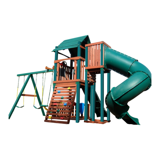
NOTE: USE THIS PLAN TO BUILD UNIT TOWER AND
TURBO TOWER. USE TURBO SLIDE PLAN FOR SLIDE
ASSEMBLY AND INSTALLATION.
PB 4447
Minimum Use Zone
30'
34'
No. of Children: Up to 12
Min. Use Zone: 34 ' x 31 '
Set Dim. 22 'W x 14 'L x 12'H
Est. Building Time: 12 hr.
check out http://www.swing-n-slide.com
for updates to these instructions.
THIS PLAN SUPERCEDES ALL
ASSEMBLY INSTRUCTIONS
BEFORE 5/21/2010
Swing•N•Slide • 1212 Barberry Drive • Janesville, Wisconsin 53545
Visit our web site at: www.swing-n-slide.com or call us at 1-800-888-1232
Advertisement

Related Manuals for Swing-N-Slide RapidLoc PB 4447


Summary of Contents for Swing-N-Slide RapidLoc PB 4447
- Page 1 Est. Building Time: 12 hr. check out http://www.swing-n-slide.com for updates to these instructions. THIS PLAN SUPERCEDES ALL ASSEMBLY INSTRUCTIONS BEFORE 5/21/2010 Swing•N•Slide • 1212 Barberry Drive • Janesville, Wisconsin 53545 Visit our web site at: www.swing-n-slide.com or call us at 1-800-888-1232...
- Page 2 When the equipment is taken out of service, it must be disassembled and disposed of in such a way that no unreasonable hazards will exist at the time the set is discarded. Important! Additional Safety Instructions for all Swing-N-Slide Playground Equipment. Save this instruction sheet in the event the manufacturer needs to be contacted.
- Page 3 Swing-N-Slide® will repair, or at its discretion, replace any part within the stated warranty period which is defective in workmanship or materials. This decision is subject to verification of the defect upon delivery of the defective part to Swing-N-Slide® at 1212 Barberry Drive, Janesville, Wisconsin, 53545. Any part(s) returned to Swing-N- Slide®...
- Page 4 TOOLS REQUIRE TOOLS REQUIRE HAMMER 1/2" & 7/16'' SOCKETS With ELECTRIC DRILL WRENCH SAFETY GLASSES CARPENTER'S SQUARE PHILLIPS and TAPE MEASURE & DUST MASK STRAIGHT BIT PB 4447 AND TURBO TOWER HARDWARE INCLUDED IN HARDWARE LIST (4) 1-3/4'' panhead screws (14) 5/16'' flat washers (2) 1/2'' panhead screws (116) 2"...
- Page 5 (2) Roof Bracket AGES 2-10 YEARS For Home / Residential Use ONLY 1212 Barberry Drive Janesville, WI 53545 1-800-888-1232 www.swing-n-slide.com (1) Name Plate with Hardware (10) Wrap-Loc (1) T20 Torx® Bit (2) EZ Frame Brackets (1) Tailor’s Chalk (1) T30 Torx® Bit...
- Page 6 ssembly Instructions (1) Super Speedwave Slide weight limit: 270 lbs. (1) Turbo Tube Slide with hardware weight limit: 250 lbs. (2) Safety Handles (1) Disc Swing (2) Heavy-Duty Swing Seat weight limit: 225 lbs. (4) Extra-Duty Swing Hangers (4) Anchor-It Straps (4) Eye Strap (1) Outrigger With Hardware...
-
Page 7: Board List
(12) 5/4'' x 4'' x 23-3/4'' (12) 5/4'' x 4'' x 36'' NOTE: (16) 5/4'' x 4'' x 40'' SWING-N-SLIDE MANUFACTURES (29) 5/4'' x 4'' x 47-1/2'' MULTIPLE KITS FROM A CENTRAL WOOD PACK. DUE TO THIS YOU MAY (2) 5/4'' x 4'' x 47-1/2'' Center Arch... - Page 8 ssembly Instructions TURBO TOWER BOARD LIST (1) 2'' x 4'' x 7'' (2) 2'' x 4'' x 8-1/4'' (3) 2'' x 4'' x 15'' N O M IN AL M AT E R IAL S IZ E (2) 2'' x 4'' x 17'' LIS T E D S IZ E T R U E S IZ E (4) 2'' x 4'' x 18''...
- Page 9 ssembly Instructions Introducing patent pending TIMBER-GLOVE™: A unique and innovative lumber wrap providing padded, splinter free uprights for residential play sets. Offered exclusively in our premium stained NO-Cut play sets. Please Note: Your unit includes Plastic Incapsulated Uprights. The TIMBER-GLOVE™ lumber wraps are not a required element for the assembly of this play set.
- Page 10 ssembly Instructions TIMBERGLOVE APPLICATION Step 1 4'' x 4'' TimberGlove TimberGlove application Step One 1. Layout your 4'' x 4'' on top of one rolled out and flattened TimberGlove. Step 2 4'' x 4'' TimberGlove TimberGlove application Step Two 2. Pull Timber Glove snug around 4'' x 4'' starting at one end and continuing to the other. Step 3 TimberGlove application Step Three 3.
- Page 11 ssembly Instructions Understanding how the Bracket System Works Example of a Shelf-Loc bracket connection. Shelf-Loc Bracket CORRECT! Wrap-Loc WRONG! Brackets ''clipped'' brackets NOT interlocked! Example of a Cup-Loc bracket connection. Top of bracket Look for ''TOP'' stamp on bracket for correct orientation. Introduction to the Bracket system Wrap-Loc 1.
- Page 12 ssembly Instructions REMEMBER: Brackets are inter-locking. Cup-loc will clip and secure into the Wrap-Loc as shown below. Insert Lag Screws ONLY where illustrated. Fig. 1 Tailor’s Chalk Repeat 4x DO NOT USE LAG SCREWS HERE Use Lag Screws Only Where Brackets Attach Fig.
- Page 13 ssembly Instructions •WARNING• Avoid splitting your Look for ‘’TOP’’ lumber by offsetting Use a 2’’ lag screw stamp on brackets to hold bracket in your screws at least while installing. place for later use. 3/4’’ from edge. Frame 1 onstruction Fig.
- Page 14 ssembly Instructions DO NOT USE LAG SCREWS HERE Use Lag Screws Only Where Frame 2 onstruction Brackets Attach Fig. 5 TIMBERGLOVE SEAM TIMBERGLOVE SEAM 2-1/2'' screws Fig. 6 per joint Fig. 6a 2'' lag screws Per Bracket 92'' 86'' 2-1/2'' screws per joint Tailor’s Chalk...
- Page 15 ssembly Instructions Fig. 7 2-1/2'' screws per joint Double check to make sure structure is square FLUSH 93-1/4'' Frame 2 Frame Construction cont. 1. Install 5/4'' and 2'' x 4'' boards as shown in (Fig 7). 2-1/2'' screw...
- Page 16 ssembly Instructions Fig. 8 Double check to make sure structure is square 2-1/2'' screws per joint 2-1/2'' screws per joint Frame Construction cont. 2-1/2'' screw 1. Install Frame 1 as shown in (Fig. 8).
- Page 17 ssembly Instructions Fig. 9 2'' lag screws Per Bracket Frame Construction (cont.) Fig. 9a 1. Install 4'' x 4'' beams as shown in (Fig. 9). 2. Install lag screws through brackets at each corner location as shown in (Fig. 9a). 2'' Lag screw...
- Page 18 ssembly Instructions Fig. 10 19-1/2'' 2-1/2'' screws per joint 2-1/2'' screws per joint 2-1/2'' screw Install Deck Boards 1. Install (2) 5/4'' x 4'' x 47-1/2'' deck boards as shown in (Fig. 10). 2. Attach (1) 2'' x 4'' x 40-1/4'' to deck boards using 2-1/2'' screws as shown in (Fig. 10).
- Page 19 ssembly Instructions Fig. 11 2-1/2'' screws per joint NOTE: There must be a 1/2'' Nominal Gap between all deck boards. 2-1/2'' screw Install Deck Boards 1. Install (8) additional 5/4'' x 4'' x 47-1/2'' and (2) 5/4'' x 4'' x 40'' deck boards to structure as shown (Fig. 11). 2.
- Page 20 ssembly Instructions Fig. 12 Fig. 13 ATTENTION: Unit has been rotated 1/4 turn Clockwise for this view. 2'' Lag screw 2'' lag screws Per Bracket Install Accessory Brackets 1. Secure Shelf-Loc brackets onto Wrap-Loc as show in (Fig. 12), (Fig. 13).
- Page 21 ssembly Instructions Fig. 14 Tip: Flex brackets to make installation of 4'' x 4'' easier Fig. 14a Approx. 1/4'' 2'' lag screws Per Bracket Fig. 15 Install Accessory 4x4 1. Work 4'' x 4'' into brackets as shown in (Fig. 14) and (Fig.
- Page 22 ssembly Instructions Swing Beam Drill Locations Fig. 16 1. Use the 3/8'' drill bit to drill a 3/8’’ hole through the 4'' x 4'' x 120'' beam at each location shown in (Fig. 16) 117-7/8'' 114-1/8'' Note: Do not use Timber Glove on Swing Beam or Swing Beam A-Frame.
- Page 23 ssembly Instructions Fig. 17 4-1/2'' CARRIAGE BOLTS FOR SWING HANGERS 4'' CARRIAGE BOLTS FOR A-FRAME WOOD LOC WASHER Swing Beam Hardware 1. Flip 4'' x 4'' Swing Beam over so that the opposite side of your drilled holes are facing upwards. 2.
- Page 24 ssembly Instructions Fig. 17b WASHER LOC-NUT WASHER LOC-NUT D-RINGS Swing Beam Drill Locations 1. Flip 4'' x 4'' Swing Beam so Carriage Bolts point downward as shown in (Fig. 17b) Swing Hangers must be installed on the same face of the Swing Beam where holes were first measured. 2.
- Page 25 ssembly Instructions Fig. 17c Loc Nut Washer Carriage Bolt 18" Fig. 17d 8" min. 8" min. A-FRAME ATTACHES HERE Fig.17e Fig. 17g Fig. 17f side view Drill 3/8" Holes 20" top view 1" 18" Outrigger Supports 1. Along top of Swing Beam mark placement for Outrigger 2'' x 4'' Supports as shown in (Fig.
-
Page 26: A-Frame Assembly
ssembly Instructions Fig. 18 A-Frame Assembly (8) 2-1/2’’ Screws 1. layout 4'' x 4’’s and 2'' x 4'' as shown in (Fig. 18). 2. Make certain to align 4'' x 4''s with the TimberGlove seams on the inside of the A- Frame (facing towards each other). - Page 27 ssembly Instructions Fig. 20 Washer 2-1/2'' screws Loc-Nut 2-1/2'' screw A-Frame Assembly cont. 1. Align EZ-Frame Bracket with carriage bolts on Swing Beam in the location shown in (Fig. 20). 2. Attach A-Frame beam to Swing Beam using (2) washers and (2) Loc-Nuts and 2 screws as shown in (Fig. 20). 3.
- Page 28 ssembly Instructions A-Frame Assembly cont. Fig. 21 1. Position Split-Brackets on 4'' x 4'' x 47-1/2'' (Fig 21). 2. With the help of others, lift A-Frame and Swing Beam Assembly and center onto unit as shown in (Fig. 21). 3. Secure as shown in (Fig 22). Fig.
- Page 29 ssembly Instructions Fig. 23 NOTE: There must be a 2'' Nominal Gap between all barrier boards. Fig. 24 Use 2-1/2'' screws to 1-1/2'' deck screws secure to 5/4'' x 4'' to 4'' x 4'' per joint 2-1/2'' screws per joint ATTENTION: Unit has been rotated 1/4 turn Counter-...
- Page 30 ssembly Instructions Fig. 25 NOTE: Secure 2'' x 4'' Boards Fig. 26 From Outside Barrier 1-1/2'' deck screws per joint 3/4'' Gap 2-1/2'' screws per joint 3/4'' Gap (2) 2' x 4'' x 36'' 2-1/2'' screws 1-1/2'' deck screws per joint NOTE: There must be a 2-1/4'' Nominal Gap between all barrier boards.
- Page 31 ssembly Instructions Fig. 28 1-1/2'' screws per joint Fig. 27 1-3/4'' (2) 5/4'' x 4'' x 36'' 2-1/2'' screws per joint 29-3/4'' 2-1/2'' screws per joint Barrier Boards cont. 1-1/2'' screw 1. Install support board as shown in (Fig. 27). 2.
- Page 32 ssembly Instructions Fig. 30 Fig. 29 2-1/2'' screws per joint NOTE: There must be a 1/2'' Nominal Gap between all deck boards. 2-1/2'' screws per joint Picnic Deck Area cont. 2-1/2'' screw 1. Install 2'' x 4'' board as shown in (Fig. 29). 2.
- Page 33 ssembly Instructions Fig. 31 Fig. 32 2-1/2'' Screws per joint 2-1/2'' Screws per joint 24-3/4'' 2-1/2'' Screws per joint 2-1/2'' Screws per joint Picnic Deck Area cont. 2-1/2'' screw 1. Install 5/4'' x 4'' boards as shown in (Fig. 31) & (Fig. 32).
- Page 34 ssembly Instructions Fig. 33 Fig. 34 1'' x 5'' x 30-3/4'' Slant Cut 1-1/2'' deck screws per joint 1'' x 5'' x 21-3/4'' Slant Cut 1-1/2'' deck screws per joint NOTE: There must be a 2-3/4'' Nominal Gap between all barrier boards.
- Page 35 ssembly Instructions 1-1/4'' deck screws 3/4'' Offset 3/4'' Offset From Edge. From Edge. Fig. 35 NOTE: Use Bracket Ribs as Guides Fig. 36 Note: No Gap Between Roof Slats. 1-1/2'' deck screws per side Roof Construction. 1-1/4'' screw 1. Align 2'' x 4'' A-Frame supports as shown in (Fig. 35). Secure in place using one (1) Metal Roof Brace.
- Page 36 ssembly Instructions Fig. 37 Fig. 38 Make Each 2'' x 4'' A-Frame Support Flush With Corresponding Upright. 1-1/2'' deck screws per joint 2-1/2'' Screws per joint Fig. 39a Fig. 39 1-1/4'' deck screw per joint, (8) per board. Note: Place screws so they go through the thickest area of the roof slat board.
- Page 37 ssembly Instructions Fig. 40a Fig. 40 (12) 5/4'' x 4'' x 40 '' Note: Center 2'’ x 4'' x 20'' Boards 2'' x 4'' x 29-3/4'' Assemblies. 2-1/2'' screws per joint 2-1/2'' deck screws per side NOTE: There must be a 1-1/4'' Nominal Gap between all Rock Wall boards.
- Page 38 ssembly Instructions Fig. 41 Fig. 41a 2-1/2'' screws per joint 2-1/2'' screw Under Deck View Climbing Rock Installation 1. Attach the Rock Wall to the unit as shown in (Fig. 41) and (Fig. 41a).
- Page 39 ssembly Instructions Fig. 42 1/4'' washer 1 - 3/4'' Panhead screw washer 1 - 3/4'' Panhead screw 11" 1 - 3/4'' Panhead screw Deck Surface Safety Handles. 1. Mount Safety Handles in the Rock Wall and Discovery Mountain openings approximately 11'' above the deck surface (Fig.
- Page 40 ssembly Instructions Fig. 43 2-1/2'' screws 14'' Install Decorative Arch Boards 2-1/2'' screw 1. Secure decorative 5/4'' Center Arch boards on both sides of unit as shown in (Fig 43).
-
Page 41: Slide Installation
ssembly Instructions Slide Installation. 1. Position slide to determine proper location for stake. 2. Drive wood stake into ground leaving 2'' exposed. 3. Secure the slide bottom to the stake using (2) 1-1/4'' deck screws. (Fig. 44a). 4. Attach slide to unit as shown in (Fig. 44). Fig. - Page 42 BEGIN TURBO TOWER CONSTRUCTION ssembly Instructions Fig. 45b Fig. 45 Fig. 45a TIMBERGLOVE SEAM 2-1/2'' screws 2'' lag screws Per Bracket 2'' lag screws Per Bracket TIMBERGLOVE SEAM 80-1/2'' Double check to make sure structure is square (3) 2-1/2'' screws DO NOT USE LAG SCREWS HERE Tip: Flex brackets to make installation of...
- Page 43 ssembly Instructions Fig. 46 2-1/2'' screws Double check to make sure structure is square 2-1/2'' screws TIMBERGLOVE SEAM 84-3/4'' 77'' 72'' 67'' 2-1/2'' screws 2-1/2'' Screw Frame Construction Cont. 1. Using (1) of the frames, install 5/4'' x 4'' boards as shown in (Fig 46).
- Page 44 ssembly Instructions Fig. 47a Fig. 47 Double check to make sure structure is square 2-1/2'' screws 2-1/2'' UNIT ROOF REMOVED Fig. 47b FOR CLARITY 2-1/2'' screws 2-1/2'' screws 2-1/2'' Screw 2-1/2'' screws Complete Frame and Secure Tower In Place 1. Attach the (2) frames as shown in (Fig. 47). 2.
- Page 45 ssembly Instructions Fig. 48 E. Tower Deck 1. Add Tower Deck Boards as shown in (Fig. 48). Note: There must be a nominal 1'' gap between all deck boards. 1-1/2'' screws Per Joint Fig. 48a Note: There must be a nominal 1'' gap between all deck boards.
- Page 46 ssembly Instructions Fig. 49 1-1/2'' screws Per Joint Note: There must be a nominal 1'' gap between all barrier boards. Fig. 49a 1-1/2'' screws Per Joint 1-1/2'' Screw Tower Barrier Installation 1. Install the barriers on the Turbo Tower as shown in (Fig.
- Page 47 ssembly Instructions Fig. 50 2-1/2'' screws UNIT ROOF REMOVED FOR CLARITY Fig. 50a 2-1/2'' screws per board 2-1/2'' screws 2-1/2'' Screw FLUSH Slide Support and Gap Filler Board 1. Install 2'' x 4'' boards around slide opening as shown in (Fig. 50). 2.
- Page 48 ssembly Instructions UNIT ROOF REMOVED Fig. 51a Fig. 51 FOR CLARITY 2-1/2'' screws per joint FLUSH Fig. 51b 2-1/2'' Screw Assemble and Install Step 1. Assemble the Step Assembly using 2'' x 4'' 2-1/2'' boards as shown in (Fig. 51). screws 2.
- Page 49 ssembly Instructions Fig. 52 Fig. 52a 2" x 4" x 7" 2" x 4" x 8-1/4" 2" x 4" x 18" 2" x 4" x 18" 2-1/2" screws Fig. 52b Fig. 52c 1-1/2" lag bolts 1-1/2" bolt support bracket washer Assemble and Attach Turbo Tube Slide, Assemble and Attach Slide Support 1.
- Page 50 ssembly Instructions Anchor-It Fig. 53a Fig. 53 Flat Washer metal strap 1-1/2" lag bolt Anchor-It Anchor-It Installation. I I n n s s t t r r u u c c t t i i o o n n s s f f o o r r A A n n c c h h o o r r i i n n g g S S w w i i n n g g • • N N • • S S l l i i d d e e A A c c t t i i v v i i t t y y C C e e n n t t e e r r s s 1.
-
Page 51: Seat Assembly
ssembly Instructions Fig. 1 UTRIGGER (2) 1-1/4'' screws SEAT ASSEMBLY. Bolt Cover 1. Place a rod cap on a hard surface. Insert steel rod into cap and tap into cap with a hammer. 2. Insert the seat section into the handle section as shown in (Fig. - Page 52 ssembly Instructions Optional Disc Swing Optional Disc Swing Optional Disc Swing 1-1/4” screws Fig. 1A Note: If you choose to install the optional Disc Swing, place in the outermost hole in the cantilever area of your swing beam. Bolt Cover Loc Nut 1.
- Page 53 ssembly Instructions...
- Page 54 ssembly Instructions...
- Page 55 ssembly Instructions...
- Page 56 Questions???... Call our Customer Service Department at 1-800-888-1232 © PlayCore Inc. 2011 Printed In USA LA 6222...
Need help?
Do you have a question about the RapidLoc PB 4447 and is the answer not in the manual?
Questions and answers