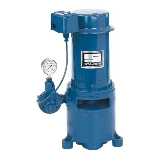
Summary of Contents for Pentair STA-RITE MS Series
- Page 1 OWNER’S MANUAL Multi-Stage Deep Well Jet Pumps 1 0 0 “MS” Series 368 1293ASB NF 293 WRIGHT STREET, DELAVAN, WI 53115 WWW.STA-RITE.COM PH: 888-782-7483 S757-1 (11/08/12) © 2012 Pentair, Ltd. All Rights Reserved.
-
Page 2: General Safety
Safety READ AND FOLLOW ELECTRICAL SAFETY SAFETY INSTRUCTIONS! Capacitor voltage may be hazardous. To discharge motor capacitor, hold insulated handle screw- This is the safety alert symbol. When you see this driver BY THE HANDLE and short capacitor terminals symbol on your pump or in this manual, look for one of together. -
Page 3: Table Of Contents
Table of Contents Page General Safety .....................2 Warranty......................3 Installation ......................4-7 Electrical ......................8-9 Operation .....................10-11 Maintenance ....................12-13 Troubleshooting ....................14 Repair Parts ....................15-16 Limited Warranty STA-RITE warrants to the original consumer purchaser (“Purchaser” or “You”) of the products listed below, that they will be free from defects in material and workmanship for the Warranty Period shown below. -
Page 4: Installation
Installation BEFORE YOU INSTALL YOUR PUMP Dirt and Scale Plug Pump and Pipes! NOTICE: For proper performance, pump MUST be matched to ejector and to well depth. Use shallow well installation for wells up to 25 ft depth to water and deep well ejector for depths up to 130 ft. Step 1. - Page 5 Installation PIPING IN THE DEEP WELL Pump Pump See Figures 7 and 8. Gasket Gasket Adapter Flange Adapter Flange NOTICE: Deep well installations are either single pipe (2” wells) or double pipe (4” and larger wells). In a double pipe installation, the larger pipe is the suction pipe and the smaller pipe is the drive pipe (very deep wells Threadless Coupling may use suction and drive pipes of the same diameter).
- Page 6 Preparing to Start the Pump – Deep Well Installation SINGLE PIPE EJECTOR INSTALLATION Pump mounted Single pipe installations require (see Figure 8): on Casing a. Galvanized steel pipe Adapter b. Leather packer-type ejector with built-in foot valve c. Turned couplings (supplied with packer-type ejector) d.
- Page 7 Installation PRESSURE TANK INSTALLATION – DEEP WELL The Pressure Tank provides a reservoir of water under pressure and Standard Tank maintains cushion of air pressure to prevent pipe hammering and possible damage to plumbing components. When water is drawn off through house Air Volume fixtures, the pressure in the tank is lowered and the pressure switch starts Control...
-
Page 8: Electrical
Electrical Disconnect power before working on pump, motor, pressure switch, or wiring. Your Motor Terminal Board (under the motor end cover) wiring if line voltage is 230 Volts or if you have a single and Pressure Switch look like one of those shown below. voltage motor. - Page 9 Electrical Connection Procedure: Step 1. Connect the ground wire first as shown in Figure Step 3. Connect the ground wire to a grounded lead in 12. The ground wire must be a solid copper wire a service panel, to a metal underground water at least as large as the power supply wires.
-
Page 10: Operation
Operation PRIMING THE PUMP NEVER run pump dry. Running pump without water may cause pump to overheat, damaging seal and possibly causing burns to persons handling pump. Fill pump with water before starting. NEVER run pump against closed dis charge, to do so can boil 1 0 0 water inside pump, causing hazardous pressure in unit and possibly scalding persons handling pump. - Page 11 Operation Step 4. Once unit has primed and pressure stabilized, slowly open (turn counterclockwise - Figure 14A) regulator valve until pressure falters (pressure gauge needle flutters; pump may become noisy - see 1 0 0 Figure 14B). At this point, close (turn clockwise) regulator valve slightly until pressure stabilizes.
-
Page 12: Maintenance
Maintenance PUMP DISASSEMBLY/ASSEMBLY Step 1. Pull disconnect switch. Disconnect power lines from pressure switch. Step 2. Remove the two cap screws holding the pump to the flange adapter. Do not disturb the piping in the well. Step 3. Remove the flange adapter gasket and scrape the surfaces clean. Step 4. - Page 13 Maintenance Step 3. Make sure that the shaft keys are in place on the shaft. If they are not, squeeze them in place now with slip joint pliers. Do not tap them or hit them with a hammer; you could bend the shaft (see Figure 21).
-
Page 14: Troubleshooting
Troubleshooting SYMPTOM POSSIBLE CAUSE(S) CORRECTIVE ACTION Motor will not run Disconnect switch is off Be sure switch is on. Fuse is blown or circuit breaker tripped Replace fuse or reset circuit breaker. Starting switch is defective DISCONNECT POWER; Replace starting switch. Wires at motor are loose, Refer to instructions on wiring (Page 8). -
Page 15: Repair Parts
Repair Parts 1 0 0 Repair Parts – MultiStage Jet Part With MSC7 MSD7 MSE7 MSF7 MSG7 Description Used 1/2 HP 3/4 HP 1 HP 11/2 HP 2 HP Motor-115/230V Single Phase A300CH A300DH A300EH Motor-230V Single Phase A300FH AE300GH Motor Canopy U18-1300 U18-1300... - Page 16 Repair Parts Item 1-Remove paper backing form gasket before applying. Item 2-Align locating lug on 1 0 0 flange with locating lug on base volute. 489 0194 Adapter Flange – (Not included with pump) Part J21626 J21627 Description Qty. 11/4x1 11/4x11/4 376 1293 Gasket...


Need help?
Do you have a question about the STA-RITE MS Series and is the answer not in the manual?
Questions and answers