
Related Manuals for Emerson Rosemount 2535


Summary of Contents for Emerson Rosemount 2535
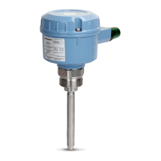
- Page 1 Quick Start Guide 00825-0100-2535, Rev AA October 2019 ™ Rosemount 2535 Solids Level Switches Vibrating Rod...
-
Page 2: Table Of Contents
Quick Start Guide October 2019 Contents Introduction..........................3 Mechanical installation.........................8 Electrical installation........................13 Configuration..........................19 Operation...........................21 Maintenance..........................22 Quick Start Guide... -
Page 3: Introduction
Equipment service needs. • 1-800-654-7768 (24 hours a day — includes Canada) • Outside of these areas, contact your local Emerson representative. WARNING Physical access Unauthorized personnel may potentially cause significant damage to and/or misconfiguration of end users’ equipment. This could be intentional or unintentional and needs to be protected against. - Page 4 Equipment ratings and certifications are no longer valid on any products that have been damaged or modified without the prior written permission of Emerson. Any continued use of product that has been damaged or modified without the written authorization is at the customer’s sole risk and expense.
- Page 5 • For information on Rosemount nuclear-qualified products, contact your local Emerson Sales Representative. Individuals who handle products exposed to a hazardous substance can avoid injury if they are informed of and understand the hazard.
- Page 6 Figure 1-1: Typical Installation Examples A. Rosemount 2535 with the tube-extended rod length B. Rosemount 2535 with the tube-extended rod length and thermal tube- extension C. Rosemount 2535 with the standard length rod D.
- Page 7 'covered' state. The electrical output will vary depending on the electronics selected when the Rosemount 2535 was ordered. Quick Start Guide...
-
Page 8: Mechanical Installation
Ensure that the process connection is tightened by the correct amount of torque and sealed to prevent process leaks. 4. Technical data a. The Rosemount 2535 Product Data Sheet has all the technical specifications. See Emerson.com/Rosemount for other language versions. - Page 9 October 2019 Quick Start Guide 2.1.2 Mechanical load The load at the mounting point must not exceed 180 Nm (Rosemount 2535 with an extended length fork). Figure 2-1: Mechanical Load A. Mounting point B. Mechanical load 2.1.3 Vertical installations Table 2-1 provides the maximum fork lengths and the corresponding maximum deviations from a normal vertical installation.
- Page 10 A suitable gasket must be fitted to provide a seal when the flanges are tightened. 2.1.7 Tightening threaded process connections When tightening the threaded process connection of a Rosemount 2535: • Use an open-ended wrench on the hexagonal boss of the level switch or the sliding sleeve.
- Page 11 October 2019 Quick Start Guide 2.1.10 Orientation of cable glands When the level switch is mounted horizontally, ensure the cable glands are pointed downwards to avoid water getting inside the housing. Unused conduit entries must be completely sealed with a suitably rated stopping (blanking) plug.
- Page 12 Quick Start Guide October 2019 Figure 2-3: Correct and Incorrect Mounting A. Full-silo detection using extended length rod option B. Empty-silo detection using extended length rod option C. Sliding sleeve option D. Bulk solids slide downwards more easily when the device is mounted at an angle (recommended) E.
-
Page 13: Electrical Installation
• Ensure the wiring is suitable for the electrical current and the insulation is suitable for the voltage, temperature, and environment. Wiring considerations Note See the Rosemount 2535 Product Data Sheet for the full electrical specifications. 3.2.1 Handling In cases of improper handling or handling malpractice, the electrical safety of the device cannot be guaranteed. - Page 14 Quick Start Guide October 2019 3.2.2 Protective earthing Before any electrical installation, the device must be connected to the protective earthing terminal inside the housing. 3.2.3 Installation regulations Local regulations or VDE 0100 (Regulations of German Electrotechnical Engineers) must be observed. When using 24 V supply voltage, an approved power supply with reinforced insulation to mains is required.
- Page 15 October 2019 Quick Start Guide Wiring diagram The electrical connections are made in accordance with the wiring diagram. Guiding the cables in the terminal box The field wiring cables must be cut to a length to be able to properly fit them into the terminal box.
- Page 16 Provide protection for relay contacts and output transistors to protect the device against inductive load surges. 3.2.12 Static charging The Rosemount 2535 must be grounded to avoid a static electrical build-up. This is particularly important for applications with pneumatic conveying and non-metallic containers.
- Page 17 October 2019 Quick Start Guide 3.2.14 Commissioning Commissioning must be performed with closed lid. 3.2.15 Opening the lid Before opening the lid, ensure no dust deposits, no airborne dusts, and no hazardous atmosphere are present. Do not remove the lid (cover) while circuits are alive. Wiring the level switch Figure 3-2: PCB Connections 3 4 5 6 7 8...
- Page 18 Quick Start Guide October 2019 Figure 3-3: Power Supply and Signal Output (Universal Voltage Version) 1 1 2 3 4 5 A. Power supply B. Signal output Wiring the 3-wire PNP Power supply: • 20 to 40 Vdc ±10% • Input current: maximum 0.5 A •...
-
Page 19: Configuration
October 2019 Quick Start Guide Configuration Adjustment of the signal output FSH setting If the sensor is used to indicate full load, set to Fail Safe High. Power failure or line break is regarded as full signal (protection against overcharging). FSL setting If the sensor is used to indicate empty load, set to Fail Safe Low. - Page 20 Quick Start Guide October 2019 Figure 4-2: Sensitivity Settings 3 4 5 6 7 8 Table 4-1: The Approximate Minimum Bulk Density Depending on the Position Position Sensitivity/Powder density (ca.) High >20 g/l (1.25 lb/ft Medium high >80 g/l (5 lb/ft Medium low >150 g/l (9.4 lb/ft >300 g/l (18.7 lb/ft...
-
Page 21: Operation
October 2019 Quick Start Guide Operation Signal output (switching logic) Figure 5-1: Switching Logic (All Versions) 3 4 5 6 7 8 3 4 5 6 7 8 3 4 5 6 7 8 3 4 5 6 7 8 A. -
Page 22: Maintenance
Quick Start Guide October 2019 Maintenance Opening the lid (cover) Before opening the lid for maintenance reasons, consider the following: • Do not remove the lid while circuits are live. • Ensure that no dust deposits or airborne dusts are present. •... - Page 23 Production date The production year is shown on the nameplate. Spare parts Refer to the Rosemount 2535 Product Data Sheet for all spare parts. Quick Start Guide...
- Page 24 The Emerson logo is a Twitter.com/Rosemount_News trademark and service mark of Emerson Electric Facebook.com/Rosemount Co. Rosemount is a mark of one of the Emerson Youtube.com/user/ family of companies. All other marks are the RosemountMeasurement property of their respective owners.
Need help?
Do you have a question about the Rosemount 2535 and is the answer not in the manual?
Questions and answers