
Related Manuals for Emerson Rosemount 2521 Series


Summary of Contents for Emerson Rosemount 2521 Series
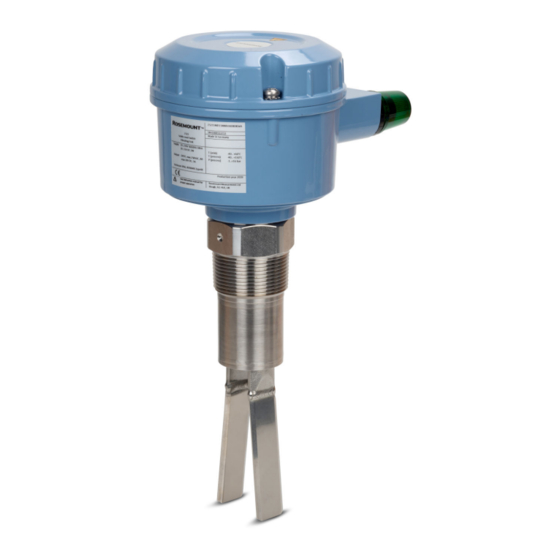
- Page 1 Quick Start Guide 00825-0100-2521, Rev AA October 2019 ™ Rosemount 2521 Solids Level Switch Vibrating Fork...
-
Page 2: Table Of Contents
Quick Start Guide October 2019 Contents Introduction..........................3 Mechanical installation.........................9 Electrical installation........................14 Configuration..........................18 Operation...........................21 Maintenance..........................22 Product certifications......................... 24 Quick Start Guide... -
Page 3: Introduction
Equipment service needs. • 1-800-654-7768 (24 hours a day — includes Canada) • Outside of these areas, contact your local Emerson representative. WARNING Physical access Unauthorized personnel may potentially cause significant damage to and/or misconfiguration of end users’ equipment. This could be intentional or unintentional and needs to be protected against. - Page 4 Equipment ratings and certifications are no longer valid on any products that have been damaged or modified without the prior written permission of Emerson. Any continued use of product that has been damaged or modified without the written authorization is at the customer’s sole risk and expense.
- Page 5 • For information on Rosemount nuclear-qualified products, contact your local Emerson Sales Representative. Individuals who handle products exposed to a hazardous substance can avoid injury if they are informed of and understand the hazard.
- Page 6 Quick Start Guide October 2019 The use of a sliding sleeve is recommended so that the switching point can be changed easily during the live operation of the level switch. Figure 1-1: Typical Installation Examples A. Rosemount 2521 with the cable-extended fork length B.
- Page 7 October 2019 Quick Start Guide Figure 1-2: Detection of solids in water A. Rosemount 2521 with the tube-extended fork length and thermal tube- extension B. Rosemount 2521 with the standard length fork C. Optional sliding sleeve D. Solids in water Measurement principles Using the principle of a tuning fork, a piezo-electric crystal oscillates the forks at their natural frequency.
- Page 8 Quick Start Guide October 2019 When the solids medium in the vessel (silo) rises and covers the fork, it causes a change of oscillation frequency that is detected by the electronics and the output switches to indicate a 'covered' state. The electrical output will vary depending on the electronics selected when the Rosemount 2521 was ordered.
-
Page 9: Mechanical Installation
Ensure that the process connection is tightened by the correct amount of torque and sealed to prevent process leaks. 4. Technical data a. The Rosemount 2521 Product Data Sheet has all the technical specifications. See Emerson.com/Rosemount for other language versions. Quick Start Guide... - Page 10 Quick Start Guide October 2019 2.1.2 Solids in Water The detection of solids in water is supported by the Rosemount 2521S only. An installation example can be seen in Figure 1-2. 2.1.3 Mechanical load The load at the mounting point must not exceed 300 Nm (Rosemount 2521 with an extended length fork).
- Page 11 October 2019 Quick Start Guide 2.1.5 Mounting location Take time to assess a suitable mounting location. Avoid mounting the level switch near the filling point, internal structures, and walls of a silo (or other vessel). When mounting the extended length versions of the level switch, it is especially important to consider internal structures.
- Page 12 Quick Start Guide October 2019 2.1.11 Rotatable housing and fork orientation mark The housing of the level switch can be rotated against the threaded connection after mounting. Figure 2-3: Housing Rotation and Fork Orientation Mark A. Threaded process connection B. Housing C.
- Page 13 October 2019 Quick Start Guide Mounting the level switch Figure 2-4 shows how the level switch should be mounted. Figure 2-4: Correct and Incorrect Mounting A. Full-silo detection using the cable-extended fork length option B. Empty-silo detection using the cable-extended or tube-extended fork length option C.
-
Page 14: Electrical Installation
Quick Start Guide October 2019 Electrical installation Safety messages WARNING Failure to follow safe installation and servicing guidelines could result in death or serious injury. • Ensure the level switch is installed by qualified personnel and in accordance with applicable code of practice. •... - Page 15 October 2019 Quick Start Guide 3.2.3 Fuse Use a fuse as stated in the connection diagrams. 3.2.4 Residual Current Circuit Breaker (RCCB) protection In case of a defect, the distribution voltage must automatically be cut-off by an RCCB protection switch to protect against indirect contact with dangerous voltages.
- Page 16 Quick Start Guide October 2019 3.2.8 Conduit system When a threaded conduit system is used instead of a cable gland, the regulations of the country must be observed. The conduit must have a ½-in. NPT tapered thread to match a NPT threaded conduit entry of the level switch and comply with ANSI B 1.20.1.
- Page 17 October 2019 Quick Start Guide Wiring the SPDT relay Power supply: • 19 to 230 Vac (50/60 Hz) +10% 8 VA • 19 to 55 Vdc +10% 1.5 W Signal output (floating SPDT relay): • Maximum 250 Vac, 8 A, non-inductive •...
-
Page 18: Configuration
Quick Start Guide October 2019 Configuration Adjustment of the signal output FSH signal output When the level switch is used to indicate full-silo, set to Fail Safe High. A power failure or line break is regarded as full-silo signal (as protection against overfilling). - Page 19 October 2019 Quick Start Guide Sensitivity The level switch is factory-set to high sensitivity (switch position B) and normally does not need to be changed. However, if the bulk solids material has a frequent tendency to cake or deposit, the setting switch can be set to position A to decrease the sensitivity of the probe .
- Page 20 Quick Start Guide October 2019 Figure 4-3: Sensitivity Settings with Potentiometer A. Potentiometer for adjusting the sensitivity B. Minimum sensitivity C. Maximum sensitivity D. Sensitivity setting is not possible Quick Start Guide...
-
Page 21: Operation
October 2019 Quick Start Guide Operation Signal output (switching logic) Figure 5-1: Switching Logic (All Versions) 3 4 5 3 4 5 3 4 5 3 4 5 A. Fail Safe High or Low setting B. Signal output Note Adjustment of the signal output for how to select a FSH or FSL setting. -
Page 22: Maintenance
Quick Start Guide October 2019 Maintenance Opening the lid (cover) Before opening the lid for maintenance reasons, consider the following: • Do not remove the lid while circuits are live. • Ensure that no dust deposits or airborne dusts are present. •... - Page 23 October 2019 Quick Start Guide Production date The production year is shown on the nameplate. Spare parts Refer to the Rosemount 2521 Product Data Sheet for all spare parts. Quick Start Guide...
-
Page 24: Product Certifications
Quick Start Guide October 2019 Product certifications EU Declaration of Conformity Figure 7-1: EU Declaration of Conformity (Page 1) Quick Start Guide... - Page 25 October 2019 Quick Start Guide Figure 7-2: EU Declaration of Conformity (Page 2) Quick Start Guide...
- Page 26 Quick Start Guide October 2019 European Union directive information The most recent revision of the EU Declaration of Conformity can be found at Emerson.com/Rosemount. China RoHS 管 管 控 控 物 物 质 质 超 超 过 过 最 最...
- Page 27 October 2019 Quick Start Guide Quick Start Guide...
- Page 28 The Emerson logo is a Twitter.com/Rosemount_News trademark and service mark of Emerson Electric Facebook.com/Rosemount Co. Rosemount is a mark of one of the Emerson Youtube.com/user/ family of companies. All other marks are the RosemountMeasurement property of their respective owners.
Need help?
Do you have a question about the Rosemount 2521 Series and is the answer not in the manual?
Questions and answers