
Related Manuals for Emerson Rosemount 2501


Summary of Contents for Emerson Rosemount 2501
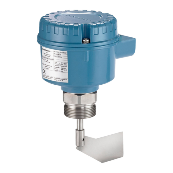
- Page 1 Quick Start Guide 00825-0100-2501, Rev AA October 2019 ™ Rosemount 2501 Solids Level Switch Rotating Paddle...
-
Page 2: Table Of Contents
Quick Start Guide October 2019 Contents Introduction..........................3 Mechanical installation.......................11 Electrical installation........................20 Configuration..........................25 Operation...........................28 Maintenance..........................31 Product certifications......................... 33 Quick Start Guide... -
Page 3: Introduction
Equipment service needs. • 1-800-654-7768 (24 hours a day — includes Canada) • Outside of these areas, contact your local Emerson representative. WARNING Physical access Unauthorized personnel may potentially cause significant damage to and/or misconfiguration of end users’ equipment. This could be intentional or unintentional and needs to be protected against. - Page 4 Equipment ratings and certifications are no longer valid on any products that have been damaged or modified without the prior written permission of Emerson. Any continued use of product that has been damaged or modified without the written authorization is at the customer’s sole risk and expense.
- Page 5 • For information on Rosemount nuclear-qualified products, contact your local Emerson Sales Representative. Individuals who handle products exposed to a hazardous substance can avoid injury if they are informed of and understand the hazard.
- Page 6 Quick Start Guide October 2019 if it has an extended length, mount it vertically on top of a silo to monitor the maximum filling limit. The length of the paddle can be up to 158 in. (4 m) with an extension tube or up to 394 in.
- Page 7 October 2019 Quick Start Guide Measurement principles Using a synchronous motor, the paddle (measuring vane) is driven to rotate 360 degrees. When the vane of the paddle is not covered by a solids medium, a spring pulls the motor and it switches a lug to the left position (Figure 1-2, top illustration).
- Page 8 Quick Start Guide October 2019 The electrical outputs vary depending on the power supply selected when the Rosemount 2501 was ordered. See the Rosemount 2501 Product Data Sheet for the Power Supply option codes, and Electronics for an overview of the outputs.
- Page 9 October 2019 Quick Start Guide 1.4.2 Shaft sealing and metal material Table 1-2: Shaft Sealing and Metal Material Application Sealing material Metal Bearing PTFE SST 304 (1.4301) Animal feed press Synthetic granules, powders Salt Dust filter (for up to 392 °F) Dust filter (for up to 302 °F) Bitumen...
- Page 10 Quick Start Guide October 2019 1.4.3 Electronics Table 1-3: Electronics Power supply SPDT DPDT FSH/ Output Fail safe delay alarm 24 or 48 Vac or version 115 or 230 Vac 24 Vdc version Universal 24 Vdc / option voltage 22 .. 230 Vac Single-Pole-Double-Throw contacts.
-
Page 11: Mechanical Installation
Ensure that the process connection is tightened by the correct amount of torque and sealed to prevent process leaks. 4. Technical data a. The Rosemount 2501 Product Data Sheet has all the technical specifications. See Emerson.com/Rosemount for other language versions. - Page 12 Maximum 180 Nm (at 40 °C) Aluminum: Rosemount 2501M and 2501K Maximum 600 Nm (at 40 °C) Stainless steel: Aluminum: Maximum 250 Nm (at 40 °C) Rosemount 2501S Contact Emerson for the maximum load of a Rosemount 2501S. Quick Start Guide...
- Page 13 Hygienic applications The food-grade materials are suitable for use under normal and predictable hygienic applications (according to directive 1935/2004 Art.3). There are currently no hygienic certifications for the Rosemount 2501. 2.1.7 Rotatable housing The housing of the level switch can be rotated against the threaded connection after mounting.
- Page 14 Quick Start Guide October 2019 Figure 2-3: Housing Rotation A. Threaded process connection B. Rotatable housing 2.1.8 Orientation of cable glands When the level switch is mounted horizontally, ensure the cable glands are pointed downwards to avoid water getting inside the housing. Unused conduit entries must be completely sealed with a suitably rated stopping (blanking) plug.
- Page 15 October 2019 Quick Start Guide Mounting the level switch Figure 2-4 shows how the level switch should be mounted. Figure 2-4: Rosemount 2501L Mounting Examples A. Angled-mounting, at top of silo, for full-silo (overfill) detection. Maximum L=23.62 in. (600 mm) B.
- Page 16 Quick Start Guide October 2019 Figure 2-5: Rosemount 2501M Mounting Examples A. Vertical-mounting for full-silo (overfill) detection with optional sliding sleeve. Maximum L=118 in. (3000 mm) B. The maximum angle of deviation from the normal vertical position is 10° when using the "bearing at tube end" option C.
- Page 17 October 2019 Quick Start Guide Figure 2-6: Rosemount 2501R and 2501S Mounting Examples A. Full-silo (overfill) detection, with a rope extension B. Demand detection, with a rope extension C. Empty-silo (filling demand), detection with a rope extension Maximum L=394 in. (10000 mm). See Mechanical load Sensitivity check the limits of the rope-extended vane (paddle).
- Page 18 Quick Start Guide October 2019 Figure 2-7: Rosemount 2501K Mounting Examples A. Horizontal mounting for full-silo (overfill) detection B. Horizontal mounting for demand detection C. Horizontal mounting for empty-silo detection A protective angle is recommended depending on the load. Quick Start Guide...
- Page 19 October 2019 Quick Start Guide Figure 2-8: Rosemount 2501J Mounting Examples A. Vertical or angled mounting, at the top of silo, for full-silo (overfill) detection B. Horizontal mounting, at the top of silo, for full-silo (overfill) detection C. Horizontal mounting for demand detection D.
-
Page 20: Electrical Installation
Quick Start Guide October 2019 Electrical installation Safety messages WARNING Failure to follow safe installation and servicing guidelines could result in death or serious injury. • Ensure the level switch is installed by qualified personnel and in accordance with applicable code of practice. •... - Page 21 October 2019 Quick Start Guide 3.2.4 Residual Current Circuit Breaker (RCCB) protection In case of a defect, the distribution voltage must automatically be cut-off by an RCCB protection switch to protect against indirect contact with dangerous voltages. 3.2.5 Power supply Power supply switch A voltage disconnection switch must be provided near the device.
- Page 22 Provide protection for micro-switch contacts to protect the device against inductive load surges. 3.2.10 Static charging The Rosemount 2501 must be grounded to avoid a static electrical build-up. This is particularly important for applications with pneumatic conveying and non-metallic containers.
- Page 23 October 2019 Quick Start Guide Wiring the ac and dc voltage versions Power supply (ac version): • 24, 48, 115 , or 230 Vac (50/60 Hz), maximum of 4 VA • External fuse: maximum 10 A, fast or slow, HBC, 250 Vac Note The supply voltage is selected when ordering the level switch.
- Page 24 Quick Start Guide October 2019 Wiring the universal voltage version Power supply (universal voltage version): • 24 Vdc ±15%, maximum 4 W • 22 to 230 Vac (50/60 Hz) ±10%, maximum 10 VA Note The voltage variances of ±10% and ±15% include the ±10% of EN 61010. Signal and alarm outputs (universal voltage version): •...
-
Page 25: Configuration
October 2019 Quick Start Guide Configuration Signal output delay Figure 4-1: Delay Timers for Signal Output Change A. Delay timer in seconds - for the switchover from a covered-to-uncovered paddle state. Factory default is 3 seconds. B. Delay timer in seconds - for the switchover from an uncovered-to-covered paddle state. - Page 26 Quick Start Guide October 2019 Adjustment of the spring The spring is adjustable in three positions. It should be changed only if necessary. Fine for light material • Medium for nearly every material (factory setting) • • Coarse for very sticky material The spring can be changed using small pliers.
- Page 27 October 2019 Quick Start Guide Sensitivity Table 4-1 shows approximate values for the minimum densities, at which a normal function should be possible. It is a guideline only for loose, non- compacted material. During a filling operation, the density of bulk material can change (e.g.
-
Page 28: Operation
Quick Start Guide October 2019 Operation Overview of the outputs For an overview of signal and alarm output for the different electronic versions, see Electronics. Signal outputs Figure 5-1: Switching Logic (Ac and Dc Versions) 7 6 5 7 6 5 A. - Page 29 October 2019 Quick Start Guide Figure 5-2: Switching Logic (Universal Voltage Version) 8 9 10 8 9 10 7 6 5 7 6 5 8 9 10 8 9 10 7 6 5 7 6 5 8 9 10 7 6 5 A.
- Page 30 B. Red, i.e. fault C. LED location on PCB Figure 5-4: Connection Example 7 6 5 4 When a Rosemount 2501 is used in a full-silo detection application with maximum safety, the output signal can indicate: • Full-silo signal •...
-
Page 31: Maintenance
October 2019 Quick Start Guide Maintenance Opening the lid (cover) Before opening the lid for maintenance reasons, consider the following: • Do not remove the lid while circuits are live. • Ensure that no dust deposits or airborne dusts are present. •... - Page 32 Quick Start Guide October 2019 Production date The production year is shown on the nameplate. Spare parts Refer to the Rosemount 2501 Product Data Sheet for all spare parts. Quick Start Guide...
-
Page 33: Product Certifications
October 2019 Quick Start Guide Product certifications EU Declaration of Conformity Figure 7-1: EU Declaration of Conformity (Page 1) Quick Start Guide... - Page 34 Quick Start Guide October 2019 Figure 7-2: EU Declaration of Conformity (Page 2) Quick Start Guide...
- Page 35 的 的 部 部 件 件 型 型 号 号 列 列 表 表 Rosemount 2501 含 含 有 有 China RoHS List of Rosemount 2501 Parts with China RoHS Concentration above MCVs / Hazardous Substances 有 有 害 害...
- Page 36 The Emerson logo is a Twitter.com/Rosemount_News trademark and service mark of Emerson Electric Facebook.com/Rosemount Co. Rosemount is a mark of one of the Emerson Youtube.com/user/ family of companies. All other marks are the RosemountMeasurement property of their respective owners.
Need help?
Do you have a question about the Rosemount 2501 and is the answer not in the manual?
Questions and answers