
Related Manuals for Kobold KAL-7000 Series


Summary of Contents for Kobold KAL-7000 Series
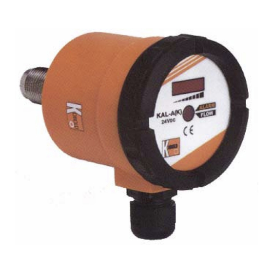
- Page 1 KOBOLD KAL-A (KAL-7000 Series) Thermal Flow Transmitter User Instructions KAL-A_manual_8-22-06...
-
Page 3: Table Of Contents
Table of Contents General Specifications Dimensions Mechanical Installation Electrical Connections Operation Calibration 5.1.1 Zero Flow Calibration 5.1.2 Adjustment of the Trend Indicator Span Flow Setpoint adjustment Setting the Transistor Switch Output Type KAL-A Diagnostics Maintenance Arrival of Damaged Equipment Need Help With Your KAL-A Getting the Most out of Your KAL-A Transmitter 10.0 Application Hint: Relay Switching with the KAL-A Transistor Switch... -
Page 5: General
General The KOBOLD KAL-A (a.k.a. KAL-7000 Series) flow transmitter is intended for use in measuring and control applications involving moderate flowrates of non-viscous or dirty liquids. The KAL-A flow transmitter uses the proven thermal dispersion principle and operates as follows: 1. - Page 6 KAL-A Electrical Specifications: Supply Power: 24 VDC ± 10%, 300 mA Max. Analog Output: 4-20 mA, 3 wire, 500 ohm Max. load imped- ance Accuracy: ±10% of full scale Repeatability: ±1% of full scale Transistor Switch (optional): Switchpoint Adjustment: By internal potentiometer Switch Type: Normally open (N/O) NPN or PNP transistor (user selectable)
-
Page 7: Dimensions
KAL-A Dimensions KAL-7215, 7315, 7320 KAL-7340S FM Rev. 8/22/06... -
Page 8: Mechanical Installation
KAL-A Mechanical Installation To install the KAL-A flow transmitter into your piping system, proceed as follows: 3.0.1 The KAL-A flow transmitter can be mounted in virtually any orientation as long as the piping is completely filled with liquid. It is recommended that the unit be installed in the upper hemisphere of the pipe when being used in horizontal piping runs. -
Page 9: Electrical Connections
KAL-A Electrical Connections Diagram 4.1 shows the layout of electrical connections, as well as other controls for the KAL-A. Diagram 4.2 shows typical electrical wiring for the KAL-A transmitter and optional transistor switch configured as either a NPN (sinking) or PNP (sourcing) transistor switch. Instructions for selecting between the PNP or NPN output are provided in section 5.3, Switch Logic Selection. -
Page 10: Operation
KAL-A Operation This section will provide details on the following aspects of KAL-A operation: • Calibration of the zero-flow reference and trend indicator span. • Adjustment of the flow switch setpoint. • Switching between PNP and NPN transistor switch output. •... -
Page 11: Adjustment Of The Trend Indicator Span
KAL-A 5.1.2 Adjustment of the Trend Indicator Span The KAL-A is factory preset to an arbitrary span value. The user must recalibrate the unit to a flow value consistent with his operating conditions. The maximum possible span corresponds to a flow velocity of 2 meters/second (6.6 feet/second). Full span flow will result in the illumination of all eight flow trend indicator LEDs and a transmitter current output of 20 mA. -
Page 12: Setting The Transistor Switch Output Type
If damage is visible, notify your local carrier at once. The carrier is liable for a replacement under these circumstances. If your claim is refused, please contact KOBOLD Instruments. FM Rev. 8/22/06... -
Page 13: Need Help With Your Kal-A
KAL-A Need Help With Your KAL-A Call one of our friendly engineers at 412-788-2830. Getting the Most out of Your KAL-A Transmitter • Microprocessor Controlled • Digital Temperature Compensation • LED Flow Trend Indicator • Analog Transmitter • Optional Flow Switch Capability •... - Page 14 KAL-A The Added Benefit of Microprocessor Controlled Temperature Compensation Thermal type flow devices measure flow by heating a probe tip immersed in liquid. As the liquid flows across the tip, the tip is cooled. The rate at which the tip is cooled is proportional to flow- rate.
-
Page 15: Application Hint: Relay Switching With The Kal-A Transistor Switch
KAL-A 10.0 Application Hint: Relay Switching with the KAL-A Transistor Switch How is it done? +24 VDC 24 VDC Relay The diagram shows the wiring interconnections 400 mA Max. Coil Current required to connect a relay coil to our transistor switch. - Page 17 KAL-A CAUTION PLEASE READ THE FOLLOWING WARNINGS BEFORE ATTEMPTING INSTALLATION OF YOUR NEW DEVICE. FAILURE TO HEED THE INFORMATION HEREIN MAY RESULT IN EQUIPMENT FAILURE AND POSSIBLE SUBSEQUENT PERSONAL INJURY. FM Rev. 8/22/06...
- Page 19 KAL-A • User's Responsibility for Safety: KOBOLD manufactures a wide range of process sensors and technologies. While each of these technologies are designed to operate in a wide variety of applications, it is the user's responsibility to select a technology that is appropriate for the application, to install it per these installation instructions, to perform tests of the installed system, and to maintain all components.
Need help?
Do you have a question about the KAL-7000 Series and is the answer not in the manual?
Questions and answers