
Subscribe to Our Youtube Channel
Related Manuals for Kobold APM-1


Summary of Contents for Kobold APM-1
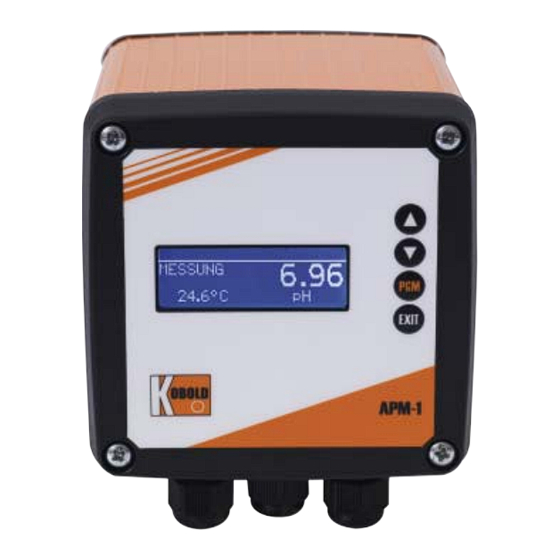
- Page 1 APM-1 Transmitter/controller for pH, redox, , temperature and standard signals Operation Instructions K03/1216...
- Page 2 WARNING: A sudden malfunction of the instrument, or one of the sensors connected to it, could potentially result in dangerous, overdosing! Suitable preventive measures must be in place to prevent this from happening. Note: Please read these Operating Instructions before placing the instrument in operation.
-
Page 3: Table Of Contents
Content Typographical conventions ............8 Warning signs ....................8 Reference signs ...................8 Description ................9 Instrument identification ............11 Nameplate ....................11 Type designation ..................12 Accessories (included in delivery) ..............13 Accessories (optional) ................13 Assembly ................. 14 General .......................14 Dimensions ....................14 Installation ................15 Installation instructions ................15 Electrical isolation ..................16 Connection ....................17... - Page 4 Content 3-point calibration ..................51 pH Antimony measurement chain ..............54 ISFET pH combination electrodes .............54 Calibrating a redox measurement chain ......55 Notes ......................55 General information ..................55 Zero-point calibration (one-point offset calibration) ........57 2-point calibration ..................58 Calibrating an ammonia measuring cell ....... 60 10.1 Notes ......................60 10.2...
- Page 5 Content Technical data ................. 94 Retrofitting optional boards ........... 97 17.1 Identifying an optional board ..............97 17.2 Removing a plug-in module ...............99 17.3 Inserting a plug-in module .................99 17.4 Retrofitting optional boards (field housing) ..........100 Appendix ................102 18.1 Glossary ....................102 18.2 Parameters of the User level ..............112 EU Declaration of Conformance ..........
- Page 6 Index Delete Display 1-point calibration - ammonia 1-point calibration - pH 2-point calibration Electrical isolation 2-point calibration - pH 3-point calibration - pH 3-point calibration . Factory settings Accessories Getting started Administrator 109 – 111 Asymmetrical connection HOLD mode Basic setting Binary inputs and outputs Info States...
- Page 7 Ooutput Optional inputs Current values Output level display Parameter overview Password Principle Principle of operation Rapid access Reference signs Setting example pH difference measurement pH measurement Setup program Simulation mode Simulation of binary outputs States Sunlight Temperature compensation User User data Warning signs Wash timer Washing contact...
-
Page 8: Typographical Conventions
1 Typographical conventions Warning signs Danger This symbol is used when there may be danger to personnel if the instructions are ignored or not followed correctly! Caution This symbol is used when there may be damage to equipment or data if the instructions are ignored or not followed correctly! Reference signs Note... -
Page 9: Description
2 Description Inputs/outputs In addition to the main input (pH/redox) and the secondary input (temperature compensation), the basic instrument alone has two binary inputs, two relays, one power supply for external sensors and a setup interface. Input signals can be shown as numbers or as a bar graph on the graphic display. - Page 10 2 Description - A choice of display visualizations: large numbers, bar graph or tendency (trend) display - Four limit controllers - Integrated calibration routines: with 1, 2 and 3 points - Math and logic module (optional) - Calibration logbook - Three optional slots - Selectable languages: English, German, French, etc.
-
Page 11: Instrument Identification
3 Instrument identification Nameplate on the transmitter VARTN: 20/00574306 APM-1E14000 F-Nr.: 0168286101012190001 ≤ 13VA AC 110..240V -15/+10% 48..63Hz AC 110..240V -15/+10% 48..63Hz ≤ 13VA VARTN: 20/00574306 F-Nr.: 0168286101012190001 The date of manufacture is encoded in the "F No." (serial number): 1122 means year of manufacture 2011 / calendar week 22... -
Page 12: Type Designation
3 Instrument identification Type designation Order Details (Example: APM-1 E 1 0 0 0 Y) Option 1 Option 2 Option 3 Model Version Housing Power supply Special (Optional board) (Optional board) (Optional board) 0 = without 1 = universal input... -
Page 13: Accessories (Included In Delivery)
3 Instrument identification Accessories (included in delivery) 4 x fastening elements, complete 3 x CON plug-in link 3 x jumper wire 1 x seal for panel 1 x fastening elements, complete - 1 x DIN rail fastening left - 1 x DIN rail fastening right - 3 x wall mount - 3 x fastening screw For basic type extension 01 only (in the panel enclosure) -
Page 14: Assembly
The instrument can be mounted in any position. position Dimensions 4.2.1 Panel mounting Close mounting Minimum spacing of panel cutouts Horizontal Vertical Without setup connector: 30 mm 11 mm With setup connector (see arrow): 65 mm 11 mm 4.2.2 Field housing EXIT APM-1 72,5 94,5 104,5... -
Page 15: Installation
5 Installation Installation instructions The electrical connection must only be performed by qualified personnel! ❏ The choice of cable, the installation and the electrical connection must conform to the requirements of VDE 0100 “Regulations on the Installation of Power Circuits with Nominal Voltages below 1000 V” and the relevant local regulations ❏... -
Page 16: Electrical Isolation
5 Installation Electrical isolation 3700 V AC semiconductor relay Setup interface Triac Binary inputs 3700 V AC Relay outputs Main input pH, redox Secondary input (Pt100/Pt1000) 30 V AC 50 V DC Power supply Continuous outputs for a 2-wire transmitter 30 V AC 30 V AC 50 V DC... -
Page 17: Connection
5 Installation Connection 5.3.1 Terminal assignment Row 1 (a) Option 1 (b) Option 2 (c) Option 3 Row 2 Main input board (pH / redox / temperature / standard signal) Row 3 PSU board (power supply / 2x relays) 5.3.2 Optional board (row 1, slot a, b or c) Function Symbol Terminal... - Page 18 5 Installation Function Symbol Terminal Terminal Terminal for slot (a) for slot (b) for slot (c) Voltage 0(2) - 10 V Voltage 0 - 1 V Continuous output Current or voltage Modbus interface RS422 RxD+ RxD- TxD+ TxD- RS485 RxD/TxD+ RxD/TxD- Profibus interface VP(+5V)
- Page 19 5 Installation Function Symbol Terminal Terminal Terminal for slot (a) for slot (b) for slot (c) Power supply for ISFET sensor DC +/- 5 V DC +12 V 5.3.3 Main board (row 2) Function Symbol Terminal Power supply for ISFET sensor DC +/- 4.85 V Standard signal input for electrical current...
- Page 20 Binary inputs Binary input 1 Binary input 2 5.3.4 PSU board (row 3) Function Symbol Terminal Power supply for APM-1 Power supply: 1 L1 (L+) AC 110 - 240 V 2 N (L-) Power supply: AC/DC 20 - 30 V n.c.
-
Page 21: Operation
6 Operation Operation via the instrument keypad is described below. Instrument operation via th e optional set-up program, See section 14 "Setup program", page 88. Controls Measurement unit Temperature Operating mode Measured value Increase numerical value / Forward selection Decrease numerical value / Forward selection Change level / Forward selection / Confirm selection Cancel entry / Exit level EXIT... -
Page 22: Display
6 Operation Display 6.2.1 Measuring mode (normal display) Example (1) Binary output (relay) K1 is active (2) Binary output (relay) K2 is active (3) Binary input is active (4) Keypad is locked (5) Instrument status ALARM (flashing): Broken sensor or overrange, etc. AL R1: Controller monitoring alarm from controller channel 1 AL R2: Controller monitoring alarm from controller channel 2 CALIB: Calibration mode active... -
Page 23: Principle Of Operation
6 Operation Principle of operation 6.3.1 Operation in levels See page Measurement mode Normal display Min/max values of the main input Min/max values of the optional inputs Output display Current values of the main input Current values of the input options Current values of the math channels States of the binary inputs and outputs Manual mode overview... - Page 24 6 Operation Display Administrator level (password) Parameter level Parameters as above for "User level" Release level Parameters as above for "User level" Basic setting Calibration level Main input (depending on the basic setting) Zero point 2-point 3-point Optional input 1, 2, 3 Temperature coefficient, linear Temperature coefficient, curve Relative cell constant...
- Page 25 6 Operation Delete total batch Calibration level 46, 55, 60 Main input Zero point 2-point 3-point Optional input 1, 2, 3 Temperature coefficient, linear Temperature coefficient, curve Relative cell constant Zero point LImit point 2-point Calibration logbook Main input Optional input 1, 2, 3 Instrument information...
-
Page 26: Measuring Mode
6 Operation Measuring mode Different display types can be configured, See "Display of measured values STANDARD" page 104. To return to measuring mode: press the key or wait for a "timeout". EXIT Measurements with "out of range" are ignored. The min./max. value memory can be reset: Administrator level / Delete min/max. -
Page 27: Input/Output Information
6 Operation Input/output information Measuring mode (normal display) < 2 s > 3 s < 2 s or timeout EXIT or timeout EXIT (adjustable) Main variable User data (adjustable) User Temperature input level EXIT or timeout (adjustable) or timeout Can only be activated with or timeout EXIT Optional input 1... - Page 28 6 Operation Measuring mode (normal display) EXIT + EXIT + EXIT + < 2 s > 3 s > 3 s Manual mode Hold mode Calibration Hardware information (controller) EXIT EXIT EXIT or timeout or timeout or timeout Keys (adjustable) (adjustable) (adjustable) release...
- Page 29 6 Operation temperature "T:" are displayed. The extreme values of the main measurement variable and the temperature are not mutually assigned (for example not 5.03 pH for 25.0°C). 6.5.3 Min/max values of the optional inputs Activating the display The instrument is in measuring mode (normal display) ✱...
- Page 30 6 Operation 6.5.6 Current values of the optional entries Activating the display The instrument is in measuring mode (normal display) ✱ Briefly press the key (several times if necessary). The current values of the optional inputs (1, 2 and 3) are displayed. 6.5.7 Current values of the math channels Activating the display The instrument is in measuring mode (normal display)
- Page 31 6 Operation 6.5.9 Manual mode overview Analog outputs (optional boards) In this example, analog outputs 2 and 3 are working normally. Switching outputs (PSU board and optional boards) In this example relay output 2 is in manual mode. The instrument is in "normal display" mode ✱...
-
Page 32: User Level
6 Operation 6.5.11 Device info These displays provide an overview of fitted hardware options and the settings of inputs (helpful for troubleshooting, etc.). ✱ Press the key for longer than 3 seconds. ✱ Briefly press the key (several times if necessary). ✱... -
Page 33: Administrator Level
All parameters can be released (modification possible) or locked (no modification possible) for editing at operator level. 6.7.3 Basic settings The APM-1 has a basic setting wizard, to make it easier for the user to configure the extensive setting options of the instrument and to avoid configuration conflicts. - Page 34 6 Operation Sensor pH standard pH antimony Redox pH ISFET-H Ammonia NH Unit for redox Unit for NH - mV - ppm - Customer-specs. - Customer-specs. Temperature-comp. source Temperature-comp. source Temperature-comp. source -Temperature input -Temperature input -Temperature input - Option input 1, 2, 3 - Option input 1, 2, 3 - Option input 1, 2, 3 - Manual temperature...
-
Page 35: Manual Mode / Simulation Mode
6 Operation 6.7.4 Calibration level Depending on which operating mode has been configured (in the Basic setting menu), one or more of the following calibration options will be available: - Zero point - 2-point calibration (only with setting "pH STANDARD" and "pH ANTIMONY"... - Page 36 6 Operation 6.8.1 MANUAL mode only via "higher order" controller functions Select manual mode In the factory setting of the instrument the MANUAL mode parameter is locked and can only be activated by the administrator! This parameter must first be released for other users, See "Release level" page 33.
-
Page 37: Hold Mode
6 Operation 6.8.2 Simulation of binary outputs Activate simulation In the factory setting of the instrument the MANUAL mode parameter is set to "No simulation" and can only be activated by the administrator! This parameter must first be released for other users, See "Release level" page 33. - Page 38 6 Operation outputs of the instrument. This means the current status of the output will be retained even when the measured value changes. Control is not via the instrument. If MANUAL mode is activated while HOLD mode is activated, MANUAL mode takes precedence and MANUAL then appears in the status line of the display! MANUAL mode can be terminated by pressing the key.
- Page 39 6 Operation Pressing a key to deactivate HOLD mode ✱ Press the keys for longer than 3 seconds. EXIT If the keys are pressed for less than 3 seconds, the instrument EXIT goes into Manual mode. Then the outputs of the instrument respond according to the default settings. Control is through the outputs of the instrument again.
-
Page 40: Commissioning
7 Commissioning Getting started Some suggestions follow for configuring the instrument reliably in little time. ✱ Mount the instrument, See section 4 "Assembly", page 14. ✱ Install the instrument, See section 5 "Installation", page 15 ff. ✱ Call up Administrator level (ADMINISTR. LEVEL). ✱... -
Page 41: Setting Examples
Setting examples 7.2.1 Measuring the pH value with pH combination electrode pH measurement with automatic temperature compensation. Layout Transmitter/controller type APM-1 pH combination electrode on the main board Coaxial cable Two-wire shielded cable Compensation thermometer Pt100 on the main board Electrical connection See section 5 "Installation", page 15. - Page 42 7 Commissioning Basic setting Start the basic settingsSee section 6.7.3 "Basic settings", page 33 Diagrammatic overview, See section "Basic setting wizard", page 33. Sensor pH standard Temperature compensation source Temperature input Reference monitoring Glass electrode monitoring Supply frequency 50 Hz Reinitialize device Temperature input Administrator level / Password / Parameter level / Temperature input...
- Page 43 7.2.2 pH differential measurement Both pH measurements are automatically temperature compensated. Layout (5a) (2a) Transmitter/controller type APM-1 pH combination electrode with 2-wire transmitter (2a) pH combination electrode on main board Two-wire transmitter on optional board 1 Two-wire shielded cable Compensation thermometer Pt100 on optional...
- Page 44 7 Commissioning Limit value control: limit value function Limit value 1: pH 6.5 Limit value 2: pH 8.5 Basic setting of main board Start the basic settingsSee section 6.7.3 "Basic settings", page 33 Diagrammatic overview, See section "Basic setting wizard", page 33. Sensor pH standard Temperature compensation source...
- Page 45 7 Commissioning Basic setting for optional board 2 Administrator level / Password / Parameter level / Optional inputs / Analog input 2 Operating mode Temperature Signal type Pt100 Connection type 2-wire Controller settings See section 13.6.1 "Simple limit monitoring", page 85.
-
Page 46: Calibrating A Ph Measurement Chain
8 Calibrating a pH measurement chain Notes During calibration, relays and analog output signals adopt their configured states! When is calibration required? - At regular intervals (depending on the sample medium and requirements). - If negative values appear in the top display. - If the top display indicates "Underrange / Overrange". - Page 47 INPUT or ANALOG INPUT. 8.2.3 Calibration options The instrument provides two calibration options for adapting the APM-1 to a pH combination electrode: One-point offset calibration The zero point of the pH combination electrode is calibrated, see section 8.3 "Zero point (1-point) calibration", page 48.
-
Page 48: Zero Point (1-Point) Calibration
8 Calibrating a pH measurement chain Zero point (1-point) calibration ✱ Make preparations, see section 8.2 "General information", page 46 . ✱ Start calibration, see section 8.2.2 "Ways to start the calibration", page 47. ✱ Select zero point calibration. ✱ Immerse the combination electrode in a buffer solution with a known pH value. -
Page 49: 2-Point Calibration
8 Calibrating a pH measurement chain then press to continue. ✱ Use the key to accept the zero point or the key to reject it. EXIT The instrument returns to measuring mode. 2-point calibration The buffer solutions (reference solutions) used for calibration must differ by at least 2 pH! During the calibration, the temperature of the two buffer solutions must be identical and remain constant! - Page 50 8 Calibrating a pH measurement chain Now the source of temperature acquisition can be selected (manually, or using the temperature input of the basic board, or the temperature input via the optional board). This source will be active for the duration of the calibration. An example follows: Manual temperature entry: ✱...
-
Page 51: 3-Point Calibration
8 Calibrating a pH measurement chain keys; then press to continue. The zero point and slope determined by the instrument are displayed. ✱ Use the key to accept the calibrated values or reject them with the key. EXIT The instrument returns to measuring mode. 3-point calibration The buffer solutions (reference solutions) used for calibration must have the following values:... - Page 52 8 Calibrating a pH measurement chain ✱ Start the 3-point calibration with the key. Now the source of temperature acquisition can be selected (manually, or using the temperature input of the basic board, or the temperature input via the optional board). This source will be active for the duration of the calibration. An example follows: Manual temperature entry: ✱...
- Page 53 8 Calibrating a pH measurement chain keys; then press to continue. ✱ Rinse and dry the combination electrode. ✱ Immerse the combination electrode in the third buffer solution with the known pH value. Wait until the display value has stabilized; then press to continue.
-
Page 54: Ph Antimony Measurement Chain
8 Calibrating a pH measurement chain pH Antimony measurement chain Antimony measurement chains are calibrated similarly to "normal" pH measurement chains. - General information on calibration See "General information" page 46. - Zero point calibration see section 8.3 "Zero point (1-point) calibration", page 48. -
Page 55: Calibrating A Redox Measurement Chain
9 Calibrating a redox measurement chain Notes During calibration, relays and analog output signals adopt their configured states! When is calibration required? - At regular intervals (depending on the sample medium and requirements). - If negative values appear in the top display. - If the top display indicates "Underrange / Overrange". - Page 56 9 Calibrating a redox measurement chain 9.2.2 Ways to start the calibration Select the input to which the pH sensor is connected. If Calibration level is not released - Press the key for longer than 3 seconds / ADMINISTR. LEVEL / PASSWORD / CALIBR.
-
Page 57: Zero-Point Calibration (One-Point Offset Calibration)
9 Calibrating a redox measurement chain Zero-point calibration (one-point offset calibration) Zero point calibration is only available if the unit is configured as "mV"! ✱ Make preparations, see section 9.2 "General information", page 55 . ✱ Start calibration, see section 9.2.2 "Ways to start the calibration", page 56. ✱... -
Page 58: 2-Point Calibration
9 Calibrating a redox measurement chain The instrument returns to measuring mode. Calibration is complete After rinsing, the combination electrode can again be used to take measurements. 2-point calibration This procedure can be used to scale the absolute input signal (mV) to a displayed relative value (%). - Page 59 9 Calibrating a redox measurement chain ✱ Rinse and dry the redox combination electrode. ✱ Immerse the combination electrode in a solution with a known "bad" redox potential. Wait until the display value has stabilized; then press continue. ✱ Set the displayed value to the relative "bad" value (in this example 80%) with the keys;...
-
Page 60: Calibrating An Ammonia Measuring Cell
10 Calibrating an ammonia measuring cell 10.1 Notes During calibration, relays and analog output signals adopt their configured states! When is calibration required? - At regular intervals (depending on the sample medium and requirements). - If negative values appear in the top display. - If the top display indicates "Underrange / Overrange". -
Page 61: Zero Point (1-Point) Calibration
10 Calibrating an ammonia measuring cell 10.2.2 Ways to start the calibration Select the input to which the sensor is connected. If Calibration level is not released - Press the key for longer than 3 seconds / ADMINISTR. LEVEL / PASSWORD / CALIBR. - Page 62 10 Calibrating an ammonia measuring cell ✱ With manual temperature entry, use the keys to set the solution temperature and confirm your entry with the key. ✱ ✱ Wait until the display value has stabilized; then press to continue ✱ Wait until the display value has stabilized; then press to continue.
-
Page 63: Calibrating A Sensor With A Standard Signal
11 Calibrating a sensor with a standard signal 11.1 General information During calibration, relays and analog output signals adopt their configured states! Sensors with a standard signal output can only be connected to an "Analog input (universal)" optional board! The sensors connected to the instrument should be cleaned and the instrument itself calibrated, at regular intervals (subject to the sample medium). - Page 64 11 Calibrating a sensor with a standard signal 11.1.2 Calibration options Different calibration options are available depending on the operating mode. Operating mode Calibration options Page 1-point 2-point Limit point Rel. Temp. cell const. coeffic. Linear Conductivity Concentration Customer specs. Due to the table with interpolation points, no calibration is required Chlorine, pH-compensated...
-
Page 65: Linear Operating Mode
11 Calibrating a sensor with a standard signal 11.2 Linear operating mode 11.2.1 1-point calibration This example is based on a liquid level measurement (as a %). The input signal is provided by a pressure transmitter. - The transmitter is in "Measuring mode". ✱... - Page 66 11 Calibrating a sensor with a standard signal Use the key to accept the value or the key to reject it. EXIT The instrument returns to measuring mode. Calibration is complete After rinsing, the sensor can again be used to take measurements. 11.2.2 Two-point calibration The values determined during calibration (zero point and slope) work out as follows:...
- Page 67 11 Calibrating a sensor with a standard signal ✱ Wait until the display value has stabilized; then press to continue. ✱ Set the displayed value to the required value (usually 0) with the keys; then press to continue. ✱ Now bring the system to a second defined state (e.g. when measuring liquid level, container full).
- Page 68 11 Calibrating a sensor with a standard signal ✱ Use the key to accept the calibrated values or reject them with the key. EXIT ✱ The instrument returns to measuring mode. Calibration is complete After rinsing, the sensor can again be used to take measurements. 11.2.3 Calibration end point This example is based on a measurement of free chlorine.
-
Page 69: Ph Operating Mode
11 Calibrating a sensor with a standard signal The slope determined by the instrument is displayed. ✱ Use the key to accept the value or the key to reject it. EXIT ✱ The instrument returns to measuring mode. Calibration is complete After rinsing, the sensor can again be used to take measurements. -
Page 70: Conductivity Operating Mode
11 Calibrating a sensor with a standard signal 11.3.2 2-point calibration This example is based on a glass combination electrode with a connected two-wire transmitter. - The transmitter is in "Measuring mode". ✱ Perform calibration, See section 8.4 "2-point calibration", page 49. 11.4 Conductivity operating mode 11.4.1 Calibration of the relative cell constant This example is based on a conductivity cell with a connected two-wire... - Page 71 11 Calibrating a sensor with a standard signal ✱ ✱ The measured conductivity value flashes on the display. ✱ Use the keys to set the value to the actual conductivity. ✱ Press the key; the relative cell constant determined by the instrument is displayed (as a ✱...
- Page 72 11 Calibrating a sensor with a standard signal 11.4.2 Calibration of the temperature coefficient Linear temperature coefficient This example is based on a conductivity cell with a connected two-wire transmitter. - The transmitter is in "Measuring mode". ✱ Immerse the conductivity sensor in the sample medium. Start the calibration, See "Ways to start the calibration"...
- Page 73 11 Calibrating a sensor with a standard signal ✱ Press the key. The conductivity (399 μS/cm) at the current temperature (24.3°C) now appears on the right of the LC display. The temperatures T1 (25°C) and T2 (70.0°C) that have yet to be triggered are shown on the left.
- Page 74 11 Calibrating a sensor with a standard signal The transmitter is in "measuring mode" and displays the compensated conductivity of the solution. Calibration is complete After rinsing, the sensor can again be used to take measurements. With non-linear temperature coefficient (TEMP. COEF. CURVE) This example is based on a conductivity cell with a connected two-wire transmitter.
- Page 75 11 Calibrating a sensor with a standard signal ✱ Heat the sample medium continuously (3) the current uncompensated conductivity (4) the current temperature of the sample medium (5) the first target temperature During calibration, the rate of temperature change in the measurement solution must not exceed 10°C/min.
-
Page 76: Concentration Operating Mode
11 Calibrating a sensor with a standard signal 11.5 Concentration operating mode 11.5.1 Calibration of the relative cell constant This example is based on a conductivity cell with a connected two-wire transmitter. The conductivity of a caustic solution is converted into a concentration value [%] by the instrument. -
Page 77: Chlorine Measurement Operating Mode, Ph-Compensated
11 Calibrating a sensor with a standard signal ✱ Use the key to accept the relative cell constant or key to reject the values. EXIT The transmitter is in "measuring mode" and displays the compensated conductivity of the solution. Calibration is complete After rinsing, the sensor can again be used to take measurements. - Page 78 11 Calibrating a sensor with a standard signal ✱ Wait until the display value has stabilized; then press to continue. Set the displayed value to the measured reference value with the keys; then press to continue. The slope determined by the instrument is displayed. ✱...
-
Page 79: Calibration Logbook
12 Calibration logbook 12.1 General information The characteristic data for the last 5 successful calibration processed are documented in the calibration logbook. Calling up The instrument is in Measurement mode. ✱ Press the key for longer than 3 seconds. Select input Briefly press the key. - Page 80 12 Calibration logbook Next most recent successful calibration ✱ Briefly press the key.
-
Page 81: Controller
13 Controller 13.1 General information Apart from faulty installation, incorrect settings on the instrument may also affect the proper functioning of the subsequent process or lead to damage. You should therefore always provide safety equipment that is independent of the instrument and it should only be possible for qualified personnel to make settings. -
Page 82: Software Controllers And Outputs
13 Controller 13.2.3 Typical operator level parameters Binary outputs Explanation Signal source No signal No switching function desired Limit control "Simple" switching functions 1 to 4 Alarm function (AF1) Alarm function (AF2) Alarm function (AF7) Alarm function (AF8) Controller 1(2) "Higher order"... - Page 83 13 Controller If "Simple controller functions" have been configured, only the digital outputs can be controlled! The operator must configure which of the digital outputs will be controlled - the main board or optional board 1, 2 or 3 Higher order controller functions Main board Optional board Simple controller...
-
Page 84: Configuration Of Higher Order Controllers
13 Controller 13.4 Configuration of higher order controllers 13.4.1 Structure Controllers Controller special functions (if necessary) Controller 1 Controller 2 Configuration Configuration Parameter set 2 Parameter set 2 Parameter set 1 Parameter set 1 Controller 1 Controller 1 Controller 2 Controller 2 Output 1 Output 2... -
Page 85: Sample Configurations
13 Controller 13.6 Sample configurations 13.6.1 Simple limit monitoring Configuration Limit monitoring Limit value 1 Signal source: Main value Switching function: Alarm function (AF8) Switching point : 6.50 pH Hysteresis: 0.50 pH Limit value 2 Signal source: Main value Switching function: Alarm function (AF7) Switching point :... - Page 86 13 Controller 13.6.2 Controller with PID behavior and pulse length output Configuration of software controllers Controller 1 Configuration Controller type: Pulse lengths Controller actual value: Main value Stroke retransmission: No signal Additive disturbance: No signal Multiplicative disturbance: No signal Min./max. contact: Min.
- Page 87 13 Controller HOLD mode HOLD output: Error: Alarm control: Parameter set 1 Min. setpoint: As required Max. setpoint: As required Setpoint: 8.50 pH Proportional range: As required Reset time: As required Rate time: As required Period time: As required Output limit: As required Min.
-
Page 88: Setup Program
- Setting a customized characteristic - etc. Data can only be transferred from or to the transmitter if it is supplied with voltage, See section 5 "Installation", page 15ff. Connection APM-1 PC interface cable with USB/TTL converter, Sales no.: ACM-Int PC or notebook... -
Page 89: Documenting The Instrument Configuration
14 Setup program 14.2 Documenting the instrument configuration Start the setup program Establish the connection to the instrument (1). Read the instrument configuration (2). -
Page 90: Special Features For "Datalogger
14 Setup program 14.3 Special features for "Datalogger" Start the setup program Establish the connection to the instrument (1). Read the instrument configuration (2). Read data from datalogger (for example table view) - Mark datalogger icon (3) - Read values from the instrument (4) - Page 91 14 Setup program Export data (for processing in an external program).
-
Page 92: Eliminating Errors And Faults
15 Eliminating errors and faults Problem Possible cause Action No measurement display There is no supply voltage Check the power supply current output Measurement display Sensor not immersed in Top up the container 0000 or medium; current output 4 mA level in container too low Flow-through fitting is blocked Clean the flow-through fitting... - Page 93 15 Eliminating errors and faults Membrane glass damaged Replace (glass) electrode. Coating Clean reference electrode. Replace reference electrode. Configuration change Configuration change Inhibit via binary contact Check configuration and unlock if necessary Do not release If appropriate release in the release level Test Inhibit via binary contact...
-
Page 94: Technical Data
16 Technical data Inputs (main board) Main input Measuring range/control Accuracy Effect of temperature range d 0.3% of range pH value -2 - 16 pH 0.2%/10°C d 0.3% of range Redox potential -1500 - 1500 mV 0.2%/10°C d 0.3% of range (ammonia) 0 - 9999 ppm 0.2%/10°C... - Page 95 16 Technical data The sensor can be monitored for short circuit and broken lead during the pH measurement by activating the impedance measurement. Impedance measurement The impedance measurement can optionally be activated. Because it depends on some boundary parameters, note the following points: - Only glass-based sensors are permitted.
- Page 96 16 Technical data Electrical data Supply voltage AC 110 - 240 V -15/+10%; 48 - 63 Hz or (switch-mode PSU) AC/DC 20 - 30 V; 48 - 63 Hz Electrical safety to DIN EN 61010, Part 1 overvoltage category II, pollution degree 2 Power consumption Max.
-
Page 97: Retrofitting Optional Boards
17 Retrofitting optional boards Caution: The instrument must be de-energized on the input and output sides! Optional boards must only be retrofitted by qualified specialists. ESD: Optional boards can be damaged be electrostatic discharge. You must therefore prevent electrostatic charges from accumulating during installation and removal. - Page 98 17 Retrofitting optional boards Optional board Code Sales No. Board view APM-100006 Semiconductor relay 1 A APM-100007 Supply voltage output +/- 5 V DC (e.g. for ISFET) APM-100008 Supply voltage output 12 V DC (e.g. for inductive proximity switch) APM-10000S Interface - RS422/485 APM-10000D Datalogger with interface...
-
Page 99: Removing A Plug-In Module
17 Retrofitting optional boards 17.2 Removing a plug-in module Squeeze the front panel together by the left and right sides and remove the plug-in module. 17.3 Inserting a plug-in module Caution: No "3" relays (2 x SPST/normally open) may be inserted in slot 2! Slot 1 for optional board Slot 2 for optional board Slot 3 for optional board... -
Page 100: Retrofitting Optional Boards (Field Housing)
17 Retrofitting optional boards Retrofitting optional boards (field housing) 17.4 1. Screw out the front cover and remove the front cover 2. Take care of the gasket 3. Screw out the electronic fastening screws (4x) and pull out the electronic , Loosen cable harness at the cable glands, if needed... - Page 101 17 Retrofitting optional boards 4. Loosen the clamp screws (4x), push back the front plate and press together the latching surface of electronic module from left and right. Pull out the electronic insert from the electronic housing. The optional boards can now be installed in the electronic. The assembly takes place in reverse order.
-
Page 102: Appendix
18 Appendix 18.1 Glossary Zero point (1-point) calibration 1 2 3 4 5 6 8 9 10 11 12 13 14 - With one-point offset calibration, the zero point of the pH combination electrode is calculated, See section 8.3 "Zero point (1-point) calibration", page 48. - Page 103 18 Appendix 3-point calibration 1 2 3 4 5 6 8 9 10 11 12 13 14 In three-point calibration, the zero point and the slope are calibrated in the acidic range and the slope is calibrated in the alkaline range, See section 8.5 "3-point calibration", page 51.
- Page 104 18 Appendix HySt Display of measured values STANDARD The measurement value, measurement variable and temperature of the measuring material are shown in standard display. Operating mode Display bottom (temperature input) Display top (analog input measurement value) Display of measured values TENDENCY The operator can quickly see the direction in which the measurement is changing.
- Page 105 18 Appendix Display of measured values BARGRAPH - Values of the main inputs, input options or math channels (signal source) can be represented as a variable bar (a bar graph). Scaling the bar ✱ Activate "BARGRAPH" as the display of measured values. ✱...
- Page 106 18 Appendix ✱ Confirm the selection with ✱ Select "SCALE END" with ✱ Use to enter the upper limit of the range to be displayed. ✱ Confirm the selection with To return to measuring mode: Press the key repeatedly or wait for a "timeout". EXIT Display of measured values LARGE DISPLAY Values of the main inputs, input options or math channels (signal source) can...
- Page 107 18 Appendix Pulse length controller (output active with x > w and P control structure) 100% Switching period Process value X Proportional band X X - W Setpoint W If actual value x exceeds setpoint W, the P controller will control in proportion to the control deviation.
- Page 108 18 Appendix Customer specs. table In this mode, the input value can be displayed based on a table (max. 20 value pairs). This function is used to display and linearize non-linear input variables. Values can only be entered in the table using the optional setup program. Cust.
- Page 109 18 Appendix This storage records the minimum and maximum input quantities that have occurred. This information can be used, for example, to assess whether the design of the connected sensor is suitable for the values that actually occur. The max./min. value memory can be reset, See section 6.7.6 "Delete min/max values", page 35: Temperature compensation The pH value of a measurement solution depends on the temperature.
- Page 110 18 Appendix the transmitter is about 1000 times greater than the impedance of the connected glass electrode. The impedance of a glass electrode may be as much as 1000 MOhm. aaaaaaaaaaaaaaaaa (1) Glass electrode (2) Reference electrode (3) Operation amplifier Symmetrical connection of pH electrodes The symmetrically high-impedance input is an alternative way to connect pH electrodes to the transmitter.
- Page 111 The impedance measurement depends on the cable material, the line length and the components used. Kobold special lines for pH measurements are limited in length to 10 m. If ISFET sensors or impedance converters are used, impedance monitoring is not possible.
-
Page 112: Parameters Of The User Level
18 Appendix 18.2 Parameters of the User level When there are numerous instrument parameters to configure, it is advisable to make a note in the table below of all the parameters to be changed and to work through these parameters in the given order. The following list shows the maximum number of parameters that can be modified. - Page 113 18 Appendix Parameter Selection / value range New setting Factory setting Unit °C/°F Without unit Cust. specs. Scaling start -100.0 - 0.0 - 499.9°C Scaling end -99.9 - 100.0 - 500.0°C Filter time constant 0.0 - 2.0 - 25.0 seconds Manual temperature -99.9 - 25.0 - +99.9°C Offset...
- Page 114 18 Appendix Parameter Selection / value range New setting Factory setting Temperature Temperature input compensation source Option input 1 Option input 2 Option input 3 Manual temperature pH compensation source Main input Option input 1 Option input 2 Option input 3 Temperature None compensation...
- Page 115 18 Appendix Parameter Selection / value range New setting Factory setting Controllers Controller 1 or 2 Parameter set 1 or 2 Min. setpoint -2.00 - 0.00 - 16.00 pH Max. setpoint -2.00 - 16.00 - 16.00 pH Setpoint -2.00 - 0.00 - 16.00 pH Setpoint 2 -2.00 - 0.00 - 16.00 pH Proportional range...
- Page 116 18 Appendix Parameter Selection / value range New setting Factory setting Stroke retransmission No signal Main value Not comp. Main value Temperature Option input 1 Option input 1 not compensated Option input 2 Option input 2 not compensated Option input 3 Option input 3 not compensated Math 1 Math 2...
- Page 117 18 Appendix Parameter Selection / value range New setting Factory setting Alarm control Controller special functions I-switch-off Inactive (the controller is working normally) Active (special behavior) Separate controllers Manual mode Locked Coding Switching Limit value control Limit values 1 to 4 Signal source No signal Main value...
- Page 118 18 Appendix Parameter Selection / value range New setting Factory setting Binary outputs Binary outputs 1 to 8 Signal source No signal Limit value control 1 Limit value control 2 Limit value control 3 Limit value control 4 Controller 1 output 1 Controller 1 output 2 Controller 2 output 1 Controller 2 output 2...
- Page 119 18 Appendix Parameter Selection / value range New setting Factory setting Analog outputs Analog outputs 1 to 3 Signal source No signal Main value Not comp. Main value Temperature Option input 1 Option input 1 not compensated Option input 2 Option input 2 not compensated Option input 3 Option input 3 not compensated...
- Page 120 18 Appendix Parameter Selection / value range New setting Factory setting Interface Modbus address 1 - 254 Baud rate 9600 19200 38400 Parity None Even Stop bits Profibus address 0 - 99 EEPROM marking Wash timer Cycle time 0.0 - 240.0 hours (0.0 = Wash contact is not active Wash time 1 - 60 - 1800 seconds...
- Page 121 18 Appendix Parameter Selection / value range New setting Factory setting Display Lighting With operation Display of measured value Standard Tendency Bargraph Trend chart Large display 3 measured values Time Display Top / Center / No signal Bottom Main value (standard for "Top") Not comp.
- Page 122 18 Appendix Parameter Selection / value range New setting Factory setting Signal source Main value Not comp. Main value Temperature Option input 1 Option input 1 not compensated Option input 2 Option input 2 not compensated Option input 3 Option input 3 not compensated Math 1 Math 2 Differential signal...
-
Page 123: Eu Declaration Of Conformance
19 EU Declaration of Conformance We, KOBOLD Messring GmbH, Hofheim-Ts, Germany, declare under our sole responsibility that the product: Transmitter/Controller pH-Value, Redox, Standard signals Temperature Model: APM-1 to which this declaration relates is in conformity with the standards noted below:... - Page 124 Manufactured and sold by: Kobold Messring GmbH Nordring 22-24 D-65719 Hofheim Tel.: +49(0)6192-299-0 Fax: +49(0)6192-23398 E-Mail: info.de@kobold.com Internet: www.kobold.com Version: K04/0919...
Need help?
Do you have a question about the APM-1 and is the answer not in the manual?
Questions and answers